This article will address several issues related to designing an excitation system for Electrical Synchronous Machines. The discussion is addressing the prime power application, such as a stationary power plant, co-generation plant in addition to the excitation system for the synchronous motor. Some of the common characteristics for most power plant applications include generators operation in parallel, operation in parallel with a utility grid, remote control of the excitation system from a control room, manual and automatic control of the excitation, and many other factors. This Best Practice will introduce several of the functions commonly used in the excitation systems.
The purpose of this article is to establish excitation system guidelines in designing, commissioning, upgrading and operation of an excitation system.
Designing Excitation Systems Guidelines – SABP-P-014 Download
Mechanical Requirements
Mechanical requirements are not always looked at first, but they are certainly very important. Since most excitation systems are purchased to international/company specifications, almost any requirement may be incorporated in the specification document, but some requirements are left general to keep the exciter system within predictable limits.
Temperature limits for most electronic equipment will allow for its use in the same ambient temperature range as the generator. Most equipment will function well up to 40ºC and down to -40ºC. If ambient conditions exceed these limits, it is necessary to control the environment where the excitation equipment will be installed, or it may be necessary to heat or cool the interior of an excitation cubicle. Of course, such temperature control will improve in reliability over the same equipment installed in an uncontrolled environment.
Moisture and high humidity can affect the operation of excitation equipment. Normally, humidity is a problem if it reaches the stage of condensation. Moisture can be a big problem for reliable operation of excitation equipment. A common practice is to include space heaters and thermostats, set to keep the temperature inside a cubicle slightly higher than the exterior ambient temperature, thus keeping humidity from condensing inside the excitation equipment.
Dust and dirt may be present in the power plant where the excitation equipment is installed. If forced air cooling is used to keep the equipment cool, filtering of the air intake may be necessary to keep dust from being drawn into the control equipment. This filter will require some maintenance to keep dirt build-up down and air flow rates up.
Electrical Requirements
Sensing Requirements
The excitation system must have means of measuring synchronous machines (generator or motor) stator voltage and current. Typically, these quantities cannot be measured directly, so it will be necessary for transformers to step down the voltage and current to useful levels for connection to the excitation system.
Caution: These transformers are not normally part of the excitation equipment and usually, they will be housed in the switchgear or the synchronous machines termination box.

Also, their secondary output may be used by other equipment in addition to the excitation equipment. The quality measurement of volts and amps must be accurate to have a good excitation system performance. The accurate should be per the burdens in IEEE/ANSI C57.13 standard for rating Potential Transformer (PT) and Current Transformer (CT) accuracy into various loads. Using metering accuracy ratings, a rating of 1.2 for a PT or CT means that at some stated burden (load) on the transformer, the secondary ratio correction factor must not exceed 1.2 percent. PT burdens are assigned letters from the alphabet; such as Y indicating a burden of 75 volt-amperes at 0.85 power factor. At burdens less than rated, the transformer is assumed to be more accurate. Thus, one can evaluate the ability of a PT or CT to perform within its necessary specifications by knowing the burden to be connected to it and the minimum acceptable accuracy for the application.
The maximum allowable error of a transformer for voltage or current sensing in an excitation system must be less than 1% of rated voltage and current.
Power to the Excitation Equipment
Some choices are available for providing ac power to the excitation system.
First source is the power from the synchronous machines terminal (shunt powered). A step-down transformer will be used to reduce the output voltage to the value needed by the excitation system. For rotary exciters, this power may be small enough to acquire single phase, or three phase source, depending on the excitation system manufacturer’s design.

The transformer is normally designed to meet IEEE/ANSI specifications for dry-type transformers
A second source of excitation power is the bus or line side of the synchronous machine breaker. See Figure 3. Using this source will allow to start the excitation without any dependence on the externally of the synchronous machines from the station battery. The bus, or line side, source must be live in order to excite the synchronous machines. This method may be used when the substation is running during the bus or line side source is available.

A third source of excitation power, used only with rotating exciters, is the Permanent Magnet Generator (PMG). (See Figure 4). Although it may be possible to install a PMG on an existing generator, usually the PMG is already mounted to the generator shaft from construction phase.

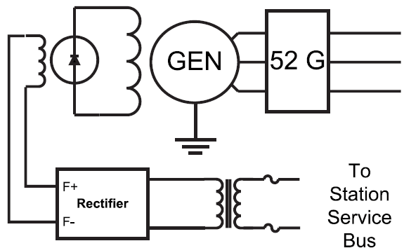
A fourth source of excitation power is a low voltage plant bus (Station Service Bus). (See Figure 5). If this source has a greater capacity when compared to the exciter power demand, for example 5 to 10 times more capacity, it is not likely to have any problems using this source. The usual reasons for using station power is to avoid the cost of an excitation transformer, eliminating the need for field flashing provisions, and inherently provide excitation support. The reason for being careful of the power capacity of the source is to keep the harmonic content of the plant bus from causing problems with other loads on the some bus. The excitation system uses techniques in switching to control power to the field, like the SCR, which potentially can cause harmonic distortion severe enough to create problems with other equipment powered from the plant bus.
Caution: Use this source with caution since it may cause harmonic distortion.
The common practice in international standards to select one of the above mentions options of powering the excitation equipment depends on the synchronous machines type (motor or generator), size and criticality of the machine. For example in case of large critical generator, brushless excitation is the third source. On the other hand, for the small synchronous motors, fourth source will be more economical.
Modes of Operation
The standard mode for controlling excitation is automatic voltage regulation (AVR). Field current regulation (VAR or PF control) or manual voltage control (MVC) are used in some cases. All of these functions will be found in modern excitation control systems. The manual control may be more sophisticated than the old rheostat used with many excitation systems. For example, it might be field current regulator supply (FCR Mode). In any case, a modern manual control must be able to back up the AVR function in case of AVR problems.
In the Generator application, the AVR normally would be equipped with means of voltage droop compensation to give the operator control of generator reactive load during parallel operation with a grid or with other generators.

For units operating in parallel with utility grids, reactive power regulation in the form of VAR Control or power factor control may be provided. This kind of control causes the unit’s output voltage to track the grid voltage as the grid changes. For small units with too little capacity to have any effect on grid voltage, one of these two modes of operation may be permissible.
With large units, however, such operation is usually discouraged because the unit under VAR or PF control will not help support the grid when voltage goes high or low. Under these conditions, the need of the grid is for all generating units to be working to assist in restoring voltage to normal value.
In the Motor application, an important advantage of a synchronous motor is that the motor power factor can be controlled by adjusting the excitation of the rotating DC field. Unlike AC induction motors which always run at a lagging power factor, synchronous motors can run at unity or even at a leading power factor. This will improve the overall electrical system power factor and voltage drop and also improve the voltage drop at the terminals of the motor. This is achieved by selecting the power factor mode in the excitation system, which is the common practice in Saudi Aramco.
Limiters
As a protective means against synchronous machine operation outside its limits, a modern excitation system will be equipped with over and under excitation limiters. Such protection becomes necessary with connection of the unit to a grid, where grid conditions can drive the generator beyond its ratings in its effort to maintain grid voltage. Also, plant transient condition can drive the synchronous motor beyond its ratings.

Excitation of a synchronous machine is limited by the heating effect of rotor field current on the field windings. Therefore, over excitation limiters monitor field excitation current. The heating of the field winding is not instantaneous; rather, the maximum continuous rating of the field is much less than the maximum 1-second or 10-second rating. If the field thermal characteristics are well known, it is possible to maximize the use of the machine capacity using a multi-level field current limiter. For example, a limiter may be equipped with two or three different levels of current limits. The highest level acts without any time delay to set the maximum value of field current under a pre-defined operating condition. If current reaches the high limit and stays at this limit for some time, the first delayed limit can reduce the field current from the instantaneous level. If field current remains at the first delayed limit for another adjustable time limit, the second delayed limit can reduce the field current to a still lower value, usually a level that the field can sustain continuously without damage.

The under excitation limit is used to maintain a minimum amount of excitation to the unit, to prevent loss of synchronism. Synchronism of the rotor to the stator frequency is dependent on the magnetic attraction of the rotor to the stator rotating magnetic field. In parallel operation with a grid, reducing excitation reduces lagging reactive power. Further reduction until reactive power has decreased to zero and the unit begins to absorb reactive power (leading power factor), causes weakening of the field magnetic attraction to the stator. A machine has some capacity for absorbing reactive power before the unit is susceptible to slipping poles. If pushed too far, it is possible for the machine to fall out of step and begin to slip poles. Operating the machine out of step will quickly cause mechanical damage to the machine and must be avoided, if at all possible.
By monitoring the machine real and reactive power load, an under excitation limiter will override the reduction in excitation current and prevent the unit from moving too far into the leading zone of operation.
Caution: In addition to normal pre-commissioning activities, two items shall be considered during the pre-commissioning:
• Coordination between the Multilin relay setting (reactive power) and excitation system limiters settings.
• Starting one of the largest motor that is fed from the same bus of the synchronous machine. This will indicate if there are any problems with the reactive power control and identify any need for limiters adjustment.
Excitation System Protection
Certain protection functions have become common as components of the excitation control system instead of being incorporated in the generator or motor switchgear.
The field ground relay is an example of an excitation related relay usually provided for the generator. (See Figure 9). Several operating ideas have been used for this relay, but a simple example is the connection of a low voltage source between one side of the field and ground. The field is supposed to be insulated from ground, so the voltage source should not cause any current to flow, and thus the relay will read insulation resistance. For insulation resistance less than 20 kilohms, a pre-alarm contact is closed. For insulation resistance less than 5 kilo-ohm, a trip contact is closed and the relay target will be set. The available current from the relay is very low, so there is no damage as a result of the relay’s small current flow through the insulation fault. It is imperative to fix the field ground before a second field ground occurs, at which time the damage to the field is likely to be extensive and expensive. Common practice is to alarm the first field ground and make repairs during at the next available shutdown.
The same equipment as that described for generators may be used if the size or importance of the motor warrants it.

The sensing voltage to the AVR is very critical, because the loss of one of the PT fuses will result in a major over excitation event. Some units are equipped with dual PT banks, using a voltage balance relay (Device 60) to detect loss of a fuse. Since relaying and metering also depend on the PT voltage, the balance relay is sometimes used to transfer loads from the failed PT to the operating PT.
In excitation control, loss of PT signal is often used to automatically transfer the control mode from AVR to manual control. Since manual control is not dependent on the feedback of generator terminal voltage, it is safe to switch to manual control until the problem with the PT signals can be resolved. If the excitation control also incorporates automatic tracking between operating modes, and if some time delay in the tracking prevents the manual mode from quickly following a faulty AVR output, the manual control will be able to take over at the same operating point that the AVR was using prior to the loss of the PT signal.
If only one PT bank is available, it is recommended to use a voltage balance and under voltage relay function to initiate a transfer from AVR to manual control, in place of the voltage balance relay. Excitation limiters also act to prevent the AVR from driving the excitation too high, but normally the limiter setting is too high to keep generator voltage under control and not used to transfer from AVR mode.

Over excitation relaying in the form of a Volts-per-Hertz (V/Hz) relay (Device 24), is usually provided as part of the switchgear generator protection package. Also, within the excitation system, a field over current rel
ay and/or a field over voltage relay function may be provided. Field current is usually preferred, because extreme field voltage variations are normal for short periods of time, so the relay needs a time delay to ride through the short term voltage variation. Field current is not quite so volatile because of the action of the field inductance that resists sudden changes in field current. It is still necessary to allow high field current to flow for short times, however, the field current relay also incorporates some time delay.
Commissioning Requirements
Getting the installed equipment up and running, eliminating errors in wiring, and seeing the new equipment operating for the first time should involve more than just the manufacturer’s commissioning engineer. The following observations shall be performed during the installation of the excitation system:
• Determining operation and protection setting will need input from the proponent organization and power distributing department.
• The logic used to put together the design may not have been totally detailed in the company specifications, leaving the exciter designer some room for design.
• Observation during the commissioning is the first opportunity for the plant personal to see how the equipment is working.
• There will often be some changes needed to get the excitation equipment to operate as expected. So, involvement from the plant people is necessary to have a successful start-up, proper calibration and settings, proper choices of operating logic and a good initial experience on this equipment.
• After everything is running, it is time to consider training of the technicians and operators on the new equipment.
• High-Potential Test Requirements for Excitation Systems for Synchronous Machines shall be performed as per IEEE Std 421.3-1997.
• All site tests shall be performed as per manufacturer recommendations.
• Coordination between the excitation system protections parameters and the main motor or generator protection (Multilin).
• For generator, the points of synchronization shall be identified.
• Also for generator installation, back- synchronization shall be considered. This is needed when the generator is isolated from the grid and power is needed to be restored from the grid.
Metering, Control and Alarms
To specify a new excitation system or replace old system the following questions on the metering, control and alarm area shall be raised:
• Specifying the interface with plant personnel is of great importance. A starting point for making these decisions is to look at the existing equipment access.
• Does the control room is the only place where metering, controls, and alarms are provided with the old equipment?
• Does the local control is provided in addition to remote control, is some kind of switching required to lock out remote control if local control is being used?
• Is there a need to operate the unit or some of its functions from a central control office using System Control and Data Acquisition (SCADA) equipment? Be sure to include your needs in the specification.
• Install metering, control switches, and annunciation to make a unit in friendly manner to utilize by any operator.
• Ask operators about problems with existing equipment that could be corrected in the new equipment.
• Develop a procedure for operators to identify the kind of interface you expect to receive with the new equipment.
• List all switches (real or computer CRT), meters, new annunciator labels, so operators can get an idea what to expect.
• Evaluate technician’s suggestions in making the equipment easy to work with them.
This is an exercise in human engineering to work out the interface requirements. This interface can be 100% operator-oriented or it can become more automated. As an example, if the unit synchronization has been done by the operators in the past, it may be beneficial evaluate automatic synchronization? There is no recipe book solution for this part of the process.
Excitation System Control
Most plants will try to keep the controls of a unit looking very familiar to the operator. There is always a need to balance new technology and old habits to find the best blend. New excitation equipment is being designed using microprocessor-based technology, but attempts are being made to keep controls compatible with operation practices.
For example, the traditional operator control for excitation has been a Raise-Off-Lower control switch, spring return to off. To adjust AVR set point, quick movements of the switch handle to “raise” and back to center is used to push the set point higher. For large changes in voltage, the operator may move the switch to the raise position and hold it there while watching the metering until the desired operating point is reached. With today’s technology, the switch may be replaced by a CRT display with a touch-screen or a mouse. Still, the operator must be able to push or make continuous adjustment depending on his needs.
This area of controlling the excitation can be specified to keep the traditional “switches and meters” approach or to move to a totally digital approach may be installed as in a Distributed Control System (DCS). The control of some parameters may be available to council operator able to observe the operation of many units and control them from location miles from the generating station.