This article is about Differential Pressure DP Type Transmitter Calibration and focusing to the engineers, technicians and supervisors. You will find lot of documents related to this article. Just navigate our website www.paktechpoint.com and find more articles. Please! Do not forget to subscribe our You tube channel also. Thanks in Advance.
Differential Pressure DP Type Transmitter Calibration
TEST EQUIPMENT USED IN CALIBRATION
1 Regulated DC power supply 24 Vdc
2 Load resistor 250 Ω ±0.005% 3W
3 Precision digital multi-meter (DVM)
4 Pressure calibrator
5 Pressure source- Compressed dry air, Nitrogen cylinders or
6 Pneumatic test pump (Fluke 700 PTP)
6 Digital HART Communicator
7 Calibrated standard test pressure gauge / manometer.
PROCEDURE OF CALIBRATION:

- Mount the transmitter on support stands firmly fixed on top of the bench.
- Vent to atmosphere low pressure side of the transmitter.
- Connect Pneumatic Pump hose tube on the port of High pressure side of the Transmitter, close the equalizing valve.
- Connect Pressure signal tube to the pressure calibrator for reference Pressure.
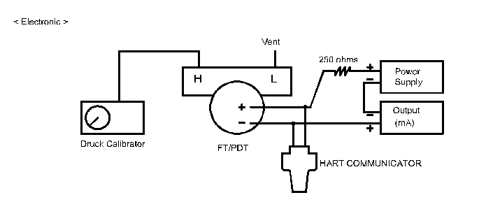
- Connect power supply 24v dc to specified transmitter terminal points, as shown in attached calibration Hook-up figure # 1A for both wiring and test equipment arrangement.
- Switch on power supply and connect the HART Communicator & DVM as shown in hoop up connection and proceed for calibration.
- Check transmitter data sheet for calibration range.
- Check the Instrument tag No, Range, and Unit are correctly configured by vendor. If not proceed to reconfigured the data as mentioned in data sheet.
- Apply pressure equivalent to lower range value of transmitter. Current out put read out should be 4.0 mA on multi-meter or pressure calibrator and 0% on the transmitter indicator. If not, proceed to Zero adjustment using the digital HART communicator.
- Apply pressure equivalent to upper range value of transmitter. Current out put read out should be 20 mA on DVM or pressure calibrator and a display of 100% on the transmitter indicator. If not, proceed to span adjustment using the digital HART communicator.
- Recheck zero after span adjustment. If it is not, repeat until both readings are correct.
- Apply reference pressures of 0%, 25%, 50%, 75% and 100% of the measurement ranges of the transmitter and check corresponding mA output for both upscale & downscale reading and do the necessary adjustments, until calibration and linearity are within specification.
- Every output reading shall be within error limit specified by manufacturer & specification. If it is not, repeat above steps until output readings are within error limit specified.
- Stick the color code sticker with signature on the transmitter as “CALIBRATED” with date.
- Record the test reading in the calibration sheet with QC inspector signature.
thanks for sharing this information.have shared this link with others keep posting such information..