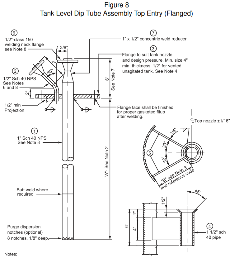
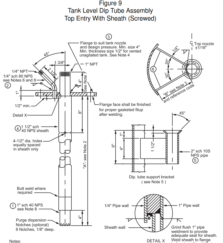
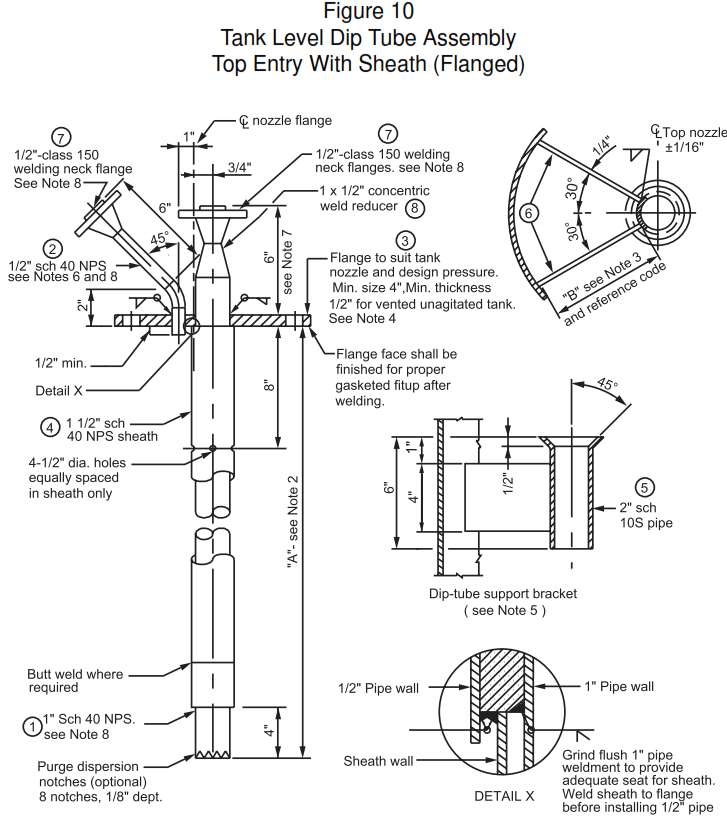
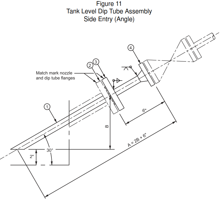
This article provides methods to determine the required purge gas flow rate and select the purge rotameter range. Equations, nomograms, and examples are included. Main keywords for this article are Dip Tubes Design Notes. Purged Dip Tube Level Measurement. Purge Rotameter. Tank Level Dip Tube Assembly. Tank Level Meter Installation.
Dip Tubes Design Notes
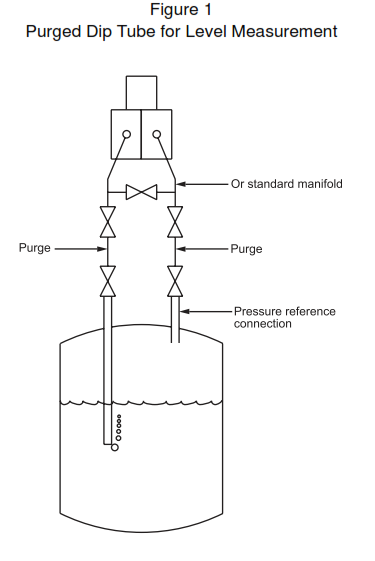
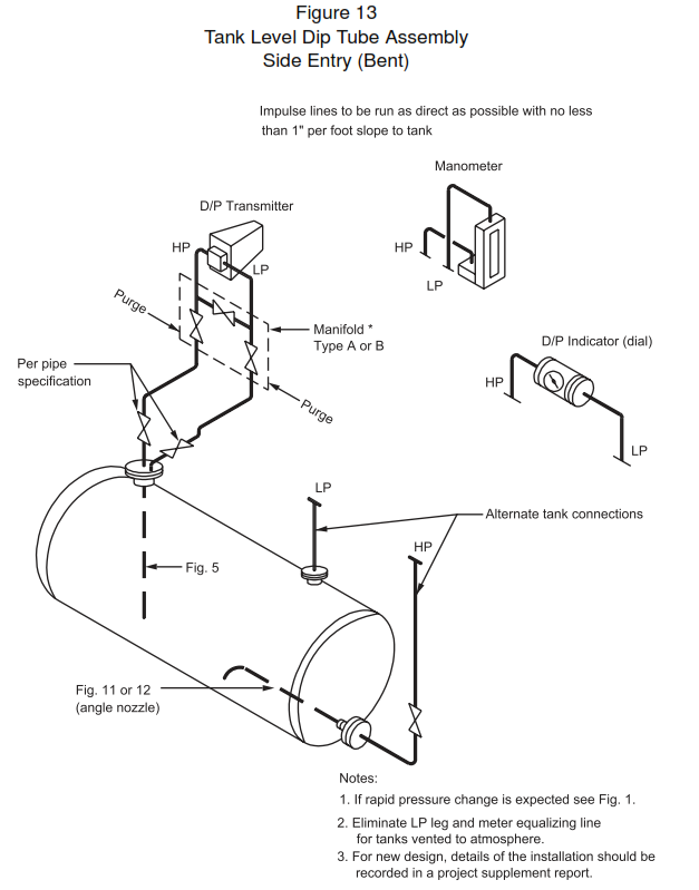
- Gas purged dip tube systems are used for vessel level and pressure measurements, see Figure 1. The gas flow rate must be sufficient to keep the system bubbling during level or pressure increase and depends upon the rate of increase, liquid density, and the volume of the system.
- Excessive flow will result in unacceptable pressure drop in impulse lines that will develop errors in pressure or level measurements and waste gas. In vacuum systems, all the gas has to be removed to maintain the vacuum.
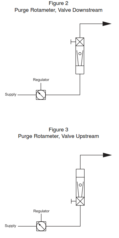
- The flow rate is usually adjusted with a flow restricting needle valve. For vessels operating at or above atmospheric pressure, the needle valve is located downstream of the meter (at the meter outlet as shown on Figure 2) and the meter operates at the regulated pressure. For vacuum systems, the needle valve is usually upstream of the meter (at the meter inlet as shown on Figure 3) and the meter operates at the lower vessel pressure.
- Where available, the regulated supply pressure should be at least twice, in absolute pressure units, the vessel pressure to develop a critical pressure drop across the restricting needle valve. This results in constant purge gas flow despite vessel pressure changes. Where this is not convenient, and supply pressure varies, a constant differential regulator across the needle valve may be used to stabilize flow.
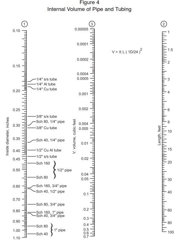
1. Calculation of purge system volume
Nomenclature
V=Purgedvolume,ft³
ID = Inside diameter of pipe or tube, in
L = Length of pipe or tube, ft
Vi = Volume of transmitter or other instrument device, ft³
2. Calculation of purge gas flow rate
Nomenclature
Qa = Required purge gas flow rate, actual, ft³ /h
V=Purged volume,ft³
∆ P/t = Pressure (or level) change per unit time, psi/h
Pd = Pressure in dip tube, psia
Pm = Meter pressure, psia
Units
- Because of the form of the equations, the choice of units is determined by the user. Typical units are shown in the equations and in examples.
- Qa has the volume units of V and the time unit is the same as that used for P/t.
- Pd, Pm,and the pressure portion of P/t must be in the same (absolute) units.
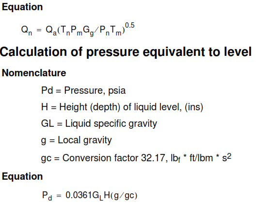
4. Calculation of meter flow
Variable area flow meter calibration is a function of gas density, and the calculated flow must be corrected to some standard conditions. The variable area meter industry has adopted a “Normal” condition of 70 °F (530 °R, 21 °C, 294 K) and 14.7 psia.
Nomenclature
Qa = Required purge gas flow rate, actual, ft³/h
Qn = “Normal” flow, cubic volume/time (ft3/h)
Tn = “Normal” temperature, 70 °F (21 °C) (294.27 K)
Pn = “Normal” pressure, 14.7 psia
Tm = Metering temperature °F (°C)
Pm = Metering pressure (psia)
Gg = Gas specific gravity
Units
Because of the ratio form of the equations, the choice of units is determined by the user. Typical units are shown. The following relationship exists:
Qa and Qn are in the same units
Tn and Tm are in the same, absolute, units
Pn and Pm are in the same, absolute, units
Precautions
- Backflow of process fluid into the purged system can be prevented by using check valves on the outlet of the rotameters (this is an option), by using nonbleed pressure regulators, and by using a reliable source of purge gas.
- For critical measurements, bottled gas has been used with check valves and regulators to back up the normal supply. A level alarm switch which does not require purge can be used to back up the purged transmitter system. In any system, the use of independent level switches should be considered to back up the primary system.
- The pressure sensor should be located above the process vessel to permit condensation to drain back to the vessel.
- Pressure impulse lines must be of adequate size to avoid plugging and to eliminate measurement errors caused by pressure drop. The usual minimum size for chemical plant use is 3/8 tubing.
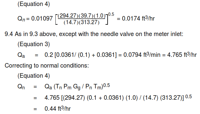
Examples
Comparing the two above examples shows the impact of inlet versus outlet needle valve locations. For lower absolute pressures the difference will be even greater.
Jacketed Pipe
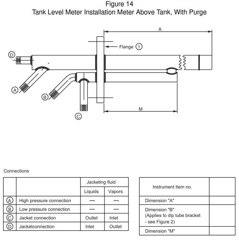
- This standard provides fabrication and other details of a jacketed dip tube designed to measure level or specific gravity in a vessel, the contents of which would plug the ends of the dip tube unless heated.
- See Figure XIII. Vapor heating medium (such as steam) is introduced through the ½-inch inlet
- connection C , and condensate is withdrawn through the ½-inch outlet connection D . For liquid heating medium, reverse of this flow is recommended.
- Materials of construction shall be as specified for the process fluid and shall be compatible with the heating medium.
- Size, weight and type of material of flange must be specified to match flange of vessel on which it will be installed. Where stainless steel or other alloys are required, carbon steel flanges clad or faced with required alloy, should be considered.
- Dimension M to be 10 inches unless otherwise specified. Establish dimension A to suit vessel.
- Maximum operating pressure – 170 psig.
- Hydrostatic test pressure of jackets – 250 psig.

