This article is one of a series of level measurement selection guide standards, specifically it describes displacement type meters. It discusses their application, suitability, advantages and disadvantages as compared to other types of level measurement. Main keywords for this article are Displacer Level Measurement, Displacer Level Application, Displacer-Type Level Instrument Installation, Displacer Level Advantages and Displacer Level Disadvantage.
Displacer Level Measurement
- Displacement type level devices can be used to measure level, density, or interface level in open, closed pressurized, or evacuated vessels. Displacement type level instruments should be purchased with a 4-inch mounting flange. When selecting an external float chamber, the chamber shall meet the process piping specification for pressure, temperature and material.
- Measurement is accomplished by sensing the buoyant force exerted upon a displacer suspended partially or fully in the process liquid.
- There are two basic type of transmitters using buoyancy as the measured variable, displacement type and float type.
- Displacement type transmitters use a displacer that is more dense than the liquid being measured and is partially or totally immersed in the liquid. This type of displacer is the subject of this standard.
- Float type transmitters, sometimes referred to as constant displacement transmitters, use a sensor that is buoyed on the surface of the liquid. This type is not part of this standard.
- Displacement instruments are of two general types, transmitters and controllers, both of which are available with electrical or pneumatic outputs.
- Displacement transmitters are devices that will transmit a signal that is linearly proportional to the liquid level being measured.
- Displacement controllers are devices that will transmit a signal that is proportional to the deviation in level about a fixed point. These devices usually have a narrow proportional operating range and some units are available with reset.
- Displacement transmitters operate on the principal that a body immersed in a liquid is buoyed upward by a force equal to the weight of the liquid displaced. If the cross-sectional area of the displacer is constant over the working length, then the buoyant force is proportional to liquid level. See Figure 1. The force is transmitted to the transmitter or controller mechanism via a force-bar or torque tube thus producing a proportional output signal.

- It is not the net force exerted on the force arm or torque tube that is important but the change in force ΔF over the level range of the liquid being measured.
- Each manufacturer will have a maximum and minimum ΔF range required to produce a full output range. In addition they will have a maximum total weight allowable for the displacer and hanger assembly.
- Since the theory of operation is based upon the amount of liquid displaced, it is imperative that the density of the displacer be greater than that of the liquid being measured.

Displacer Level Application
- Displacement measuring devices are available in a wide variety of mounting configurations and orientations. They can be easily installed or removed and require little or no routine maintenance. This, together with the wide range of pressure and temperature limits and the high accuracy achievable, make them candidates for consideration in many level control applications. Typically, displacement type level transmitters may be applied where ranges are 48 inches (1200 mm) or less, where fluid densities vary significantly, or where operating pressures vary significantly. For liquid level or liquid to liquid interface level measurement – ranges are determined by displacer length; standard displacers are available for ranges 0 to 14 inches up to 0 to 120 inches (0 to 356 mm up to 0 to 3048 mm). For density measurements – displacer volume determines upper range limit of the change in density.
- Accuracy or reliability of a displacer installation can be affected by the turbulence of the liquid in which it is immersed. Guards may be installed around the displacer to minimize or eliminate this effect. Displacement type level instruments shall not be applied for high viscosity materials or where the liquid surface is in violent agitation. Internal Ball Floats and Differential Pressure devices shall be supplied, respectively, for these conditions.
- In most applications, the use of external chambers is preferred over guarding the displacer or suspending it freely in the liquid. Proper use of the external chamber and associated valving will permit removal of the transmitter or displacer (or both) for service without disrupting process operation.
- The length of the displacer needs to be as long as the range of levels to be measured. An additional 10 to 20 percent should be added to this length to allow for errors in positioning.
Caution: The displacer must never contact the bottom of a vessel or any buildup that may form. Allow sufficient clearance to prevent this from happening.
The volume of the displacer required to produce a ΔF can be found by:
V = ΔF / (0.036 x SG) in³
Where:
V = Volume, in³
ΔF = Force change (instrument requirement), pounds
SG = Specific gravity of liquid
0.036 = Weight of 1 cubic inch water, lb/in or from the chart of Figure 2.

The outside diameter of the displacer can be estimated from Figure 3 or calculated by the simple equation:
d = 2 √ L/V
Where:
d = Diameter of displacer, in
L = Length of displacer, in
The force change ΔF for the different applications of a displacement instrument can be easily calculated. This force must fall within the minimum and maximum values specified by the manufacturer.

- Liquid Level Applications. Liquid level measurement is accomplished by permitting the liquid surface to vary over the length of the displacer.
The ΔF for this type of application is:
ΔF = v ( ) x 0.036 x SG
Where:
V = Volume of the displacer, in³
h = Range of level required, in
L = Total length of displacer, in
SG = Specific gravity of liquid - Interface Level Applications. When measuring interface level, it is essential that the displacer be completely immersed in the liquid. The measurement is made by allowing the interface level to vary over the length of the displacer.
The ΔF for this type of application is (see Figure 4):
Δ – 0.036 V (SG2 – SG1 )
Where:
V = Total volume of displacer, in³
SG2 = Specific gravity of lower liquid
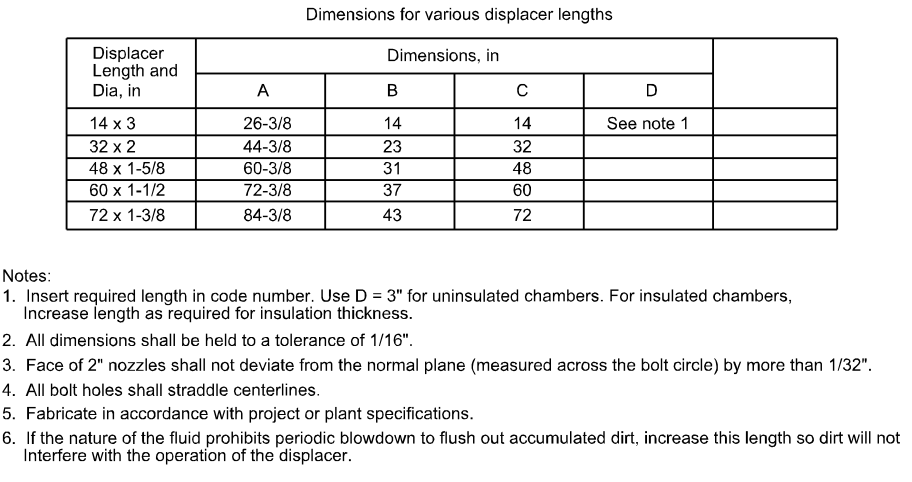
SG1 = Specific gravity of upper liquid - Refer to Figures 5 to 9 for selection of materials of construction and installation methods.


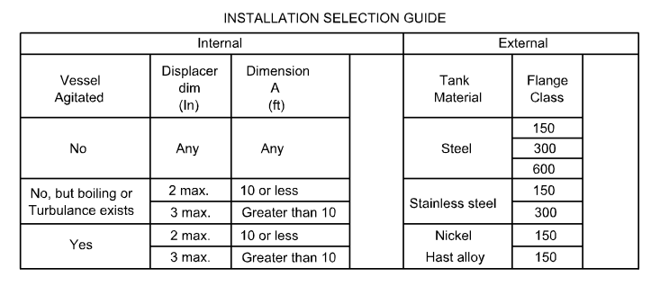
FIGURE 6 – Displacer-Type Level Instrument Installation, Type C Guard, 4-inch Nozzle

FIGURE 7 – Displacer-Type Level Instrument Installation, Type D Guard, 4-inch Nozzle

FIGURE 8 – Level Chamber, Displacer Type, 4 inch, Type A, Steel

Displacer Level Advantages
- Displacement devices can be used over a wide range of temperatures and pressures.
- These instruments can be calibrated quickly and accurately. Some can be calibrated without removal from the vessel.
Displacer Level Disadvantage
- Displacement devices should not be used where accumulation of solids can build up on the displacer surface. This would have the effect of increasing the volume of the displacer and changing the calibration.
- Changes in the specific gravity of the liquid can cause errors in the level measurement..
- A substantial amount of additional cost may be required to eliminate turbulent liquid effects.