This article is to guide the responsible persons in conducting Distance or Impedance Protection Relay (21) Commissioning and test. Testing and commissioning a distance or impedance protection relay (21) involves ensuring the relay accurately measures the impedance to a fault and operates correctly to isolate the faulted section of the power system.
Test Equipment: Secondary Injection test kits; Multimeter; Digital Timer.
Safety Precautions: The following Safety precautions shall be taken in consideration prior, during and after conducting the test measurements.
- Safety tagging shall be implemented.
- Isolate the Area by Safety Warning Tape.
- Keep a Safe Distance from the device being tested.
- Wear Appropriate Personal Protective Equipment (PPE) Prior to starting any testing activity.
- Implementation of Proper Grounding.

Distance or Impedance Protection Relay (21) Test & Commissioning.
- Perform General Visual Inspection.
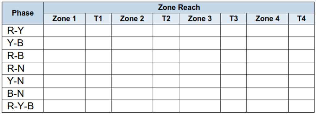
- Check all Zones reaches & Time Testing for all phases and all types of faults.
2.1 Perform the tests required as per the following test connection for injection of secondary impedance values to the relay:
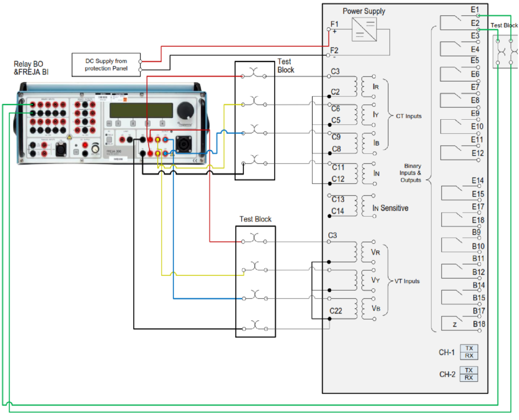
2.2 Inject of secondary impedance values and Check all Zones reaches & Time Testing for all phases and all types of faults.
2.3 Record the Results in the below table as per test forms.
3. Permissive Under reach transfer trip (PUTT) Test.
3.1 Perform the tests required as per the following test connection for injection of secondary impedance values to the relay:
3.1 Signal Send Z1.Simulation of permissive underreach transfer trip(PUTT) from the injected secondary impedance zone 1 value to the relay.
 Test.")
3.2 Record the Results in the table shown at the right or as required in test forms.
4. Permissive Over reach transfer trip (POTT) Test.
4.1 Perform the tests required as per the following test connection for injection of secondary impedance values to the relay:
4.2 Signal Send Z2. Simulation of permissive overreach transfer trip(POTT) from the injected secondary impedance zone 2 value to the relay.
4.2.1 If the fault is between SS1 & SS2, There is signal transmitted between protection
relays for different feeders.
4.2.2 Record the Results in the table shown at the right or as required in test forms.
4.2.3 If the fault is outside SS2, There is no signal transmitted between protection relays for different feeders.
 Test.")
4.3 Signal Send Z3. Simulation of permissive overreach transfer trip(POTT) from the injected secondary impedance zone 3 value to the relay.
 Test.")
5. Blocking Scheme Test.
5.1 Perform the tests required as per the following test connection for injection of secondary impedance values to the relay:
5.2 Simulation of Blocking scheme from the injected secondary impedance zone 4(reverse zone) value to the relay.

5.3 Record the Results in the table shown at the right or as required in test forms.
5.4 Signal Send Z1.

5.5 Record the Results in the table shown at the right or as required in test forms.
6. Checking of Echo Only and Trip.
6.1 Perform the tests required as per the following test connection for
injection of secondary impedance values to the relay:
6.2 Simulate the tests required as per the following diagram for injection of secondary impedance zone 1 value to the relay with its corresponding CB closed in SS3 and the CB should be Open in SS4:

7. Power Swing Test.
7.1 Perform the tests required as per the following test connection for injection of secondary impedance values to the relay:
7.2 Inject secondary impedance values as margin zone characteristics for the relay.
7.3 If the operating point stays within the margin zone characteristics, the relay initiates blocking and LED configured power swing blocking should indicate.
7.4 Record the measured margin zone and draw the power swing blocking characteristics.

8. Switch on to Fault (SOTF) Test.
8.1 Perform the tests required as per the following test connection for
injection of secondary impedance values to the relay:
8.2 Inject secondary impedance values and Check all Zones reaches & Time Testing for all phases and all types of faults.
8.3 Continue to Inject the secondary secondary impedance values and close the circuit breaker to check Switch On to Fault(SOTF).
8.4 Connect the circuit breaker SOTF Operated and LED for SOTF Operated and circuit breaker is not connected.
8.5 Record the Results in the below table as per test forms.
 Test.")
9. VT Supervision Relay (VT Fail) Test.
9.1 Perform the tests required as per the following test connection for
injection of secondary impedance values to the relay:
9.2 Inject secondary 3phases current and Zero voltage (No Phases voltage).
9.3 VT FAIL Operated and LED for VT FAIL Blocking Operated.
9.4 Inject secondary 3 phases current and 2 phases voltage.
9.5 VT FAIL Operated and LED for VT FAIL Blocking Operated.
9.6 Inject secondary 3 phases current and 1 phase voltage.
9.7 VT FAIL Operated and LED for VT FAIL Blocking Operated.
9.8 Record the status of VT FAIL.
Following manufacturer specific testing procedures and adhering to industry standards and guidelines are crucial for conducting accurate distance or impedance protection relay testing and commissioning. Qualified personnel with expertise in protective relaying should perform these tasks.