This Article covers the minimum requirements for the design, configuration, and installation of Distributed Control Systems (DCS).
1. Scope
This article shall be used as a guide in conjunction with SES-X02-G01 to develop project specific Distributed Control Systems. This standard does not relate to any specific brand name but refers to general standards and industry practices.
2. References
Reference is made in this article to the following documents.
X01-E01 Control System Design Criteria
X02-G01 Distributed Control System Implementation Guidelines
X05-E03 Foundation Fieldbus Implementation
American National Standards Institute / Institute of Electrical and Electronics Engineers (ANSI/IEEE)
C37.90.1 Surge Withstand Capacity Test
International Society of Automation (ISA)
SP 88 Batch Standards
ISA 71.04 Environmental Conditions for Process Measurement and Control Systems: Airborne Contaminants
International Electrotechnical Commission
IEC 61131-3 Programming Languages
3. Distributed Control System Definitions
Application Software. Software written functions specific to an operating unit, plant, or project. Application software does not modify standard software, but works along with it.
Availability. Probability that a system will be able to perform its designated function when required.
Control Network. Ethernet network where process control data is handled among the controllers and workstations.
Controller. Module capable of performing full control of the process with process control algorithms, and manage data acquisition and interaction with the process via its input/output modules.
Control Processor. Microprocessor that performs controller‟s functions.
Console. Logical grouping of workstations and associated equipment used by the operator/supervisor/engineer to interface with the process.
Discrete Control. Control where inputs, algorithms and outputs are based on logical (Yes or No) functions, for example pump auto start/stop.
Faceplate. Graphic element in the DCS display that mimics the front panel of an analog controller, indicator, or hardwired switch.
Firmware. Programs or instructions, that are permanently stored in the hardware memory.These are usually Read Only Memory (ROM) and cannot be changed by the user.
Logs. Files or printouts of information in chronological order
Mode. Control block mode, for example manual, auto, and cascade
Module. Assembly of interconnected components that constitute a device, or piece of equipment. Typically in a DCS system it will be printed circuit board that can be mounted in a file
chassis. A module has definable performance characteristics which can be tested.
Node. Each element of the DCS that has a dedicated role in system philosophy, and has connection to control network, e.g. Controller, Workstations, Servers, etc.
Redundancy. System configuration with two or more identical modules that provides automatic switchover in the event of a failure of one of the modules, without loss of system function.
Regulatory Control. Combination of process measurement, control calculation, and final control device manipulation that provide closed loop control.
Reliability. Probability that the system or component will perform its intended function for a specified period of time.
Scan Period. Time in which CPU of the controller executes the standard control functions.
Scan Cycle. Total time to scan inputs, execute control algorithms, and transmit outputs to field devices.
Self-diagnostics. Capability of an electronic system to monitor its own status and indicate faults that occur within the device.
System Alarm. Alarm, which occurs as result of a DCS hardware or software fault System Operating Software. Vendor‟s standard software that performs the basic function of the system
Tag (tagname/ tag number). Collection of attributes that specify, for example, a control loop, process variable, set point or control algorithm. Each tagname is unique to a plant.
Third-Party System. Any control and/or instrumentation equipment which is manufactured/supplied by other than DCS VENDOR, and which requires integration or digital
communication with the DCS.
Workstation. Microcomputer designed for technical applications.
Abbreviations and Acronyms
EMI Electromagnetic Interference
EWS Engineering Workstation
FAT Factory Acceptance Test
I/O Inputs and Outputs
LCD Liquid Crystal Display
MIS/PIMS Management Information System, Plant Information Management System
MTBF Mean Time between Failures
MTTF Mean Time to Failure
OWS Operator Workstation
PID Proportional, Integral, and Derivative control modes
4. System Overview and Distributed Control System Specification
4.1 Conceptual System Architecture
DCS shall be based on “open” system architecture. That is the system shall maximize the use of general purpose computing hardware and software products and have inherent capability to integrate and exchange information with other brand software packages, system devices and platforms via industry standard communications, platforms and protocols.
The DCS conceptual system architecture shall include operator workstations, engineering workstations, controllers, I/O networks, bulk storage devices, e.g. hard drives, and backup storage devices, third party interfaces, and output devices e.g. B&W and color printers. The system architecture shall provide the necessary hardware to satisfy the needs of the following major functions:
4.1.1 Human Machine Interface (HMI)
Operator workstations for HMI shall be robust, reliable workstations equipped with LCD-based single, double or four screens, capable of displaying DCS information and other systems connected to the DCS.
4.1.2 Process Interface
Interface to the process shall be through distributed microprocessor-based control modules. Each controller shall be a standalone unit capable of performing full data acquisition and control of the process via local or remote I/O modules.
4.1.3 Engineering Workstation (EWS)
The EWS shall be a high performance workstation capable of engineering and configuring any DCS device linked to the control network.
4.1.4 Communication Network
High speed redundant networks shall be provided for connectivity of all the components of the DCS to perform real time and historical information transfer between various components. Different layers shall provide segregation among different parties of the whole network.
4.1.5 Interface with third party systems
Third party interface shall be based on industrial standards. OPC, wherever available, tested and proven, is the preferred interoperability standard by SABIC. Any non-OPC compliant application serial interface, Modbus-RTU, Modbus-TCP shall be approved by Company. Proprietary interfaces shall not be used.
4.1.6 Peripherals and Servers
The system shall include all necessary modules for bulk memory and removable storage media, B&W and color printers where specified.
4.1.7 Open System Server
DCS shall be equipped with an OPC server to provide connections and bi-directional data transfer to any third party OPC client applications.
4.1.8 MIS/PIMS
It shall be implemented to serve plant process data in appropriate formats to concerned departments, e.g. operations, maintenance, etc.
4.2 System Functionality
4.2.1 Technology
The system shall be made up of manufacturer‟s standard hardware, firmware, and software that can be configured to meet stated requirements.
4.2.2 System Lifecycle and Expandability
a. Vendor shall provide support from design through installed life of the system.
b. He shall also advise expected length of time system components (hardware, software) will be manufactured and supported. Normally company expects a minimum of 10 years support from the time of purchase order date, and that the vendor has a local office with sufficient staff able to respond to the needs of the plant.
c. During the warranty period vendor shall ensure to inform SABIC about the future upgrades. However, FAT shall be carried out with the latest proven version at the time of hardware freeze.
d. The system shall be modular in design providing flexibility to economically implement small projects but scalable for expansions and major projects.
e. It shall be possible to add and remove nodes, controllers, I/O modules, consoles and workstations, online without shutting down the system.
4.2.3 Redundancy
a. A single point failure anywhere in the system shall not prevent the operator‟s ability to monitor and control the process.
b. Single point failure anywhere in the system shall not result in the loss of a control loop. System shall function by switching over to backup modules to accomplish control.
c. All controller modules and control loop associated I/O modules shall be provided in redundant configuration. This will provide uninterrupted control in the event of a loss of a single module.
d. Control networks shall be fully redundant including, but not limited to, all controllers, network interface cards, routers, switches, firewalls and cabling.
e. Transfer to the secondary device shall be automatic and bumpless. The system shall provide the operators with an appropriate alarm message. The vendor should advise the standard time of switch-over between redundant components, in case of failure.
f. Unless specified, monitoring only points‟ input modules shall not be provided in redundant configuration, but their hardware modules shall be capable of being redundant without replacing the hardware.
g. All controller cabinet power supplies shall be supplied in redundant configuration.
h. Provisions shall be provided to switch over to redundant equipment by manual means. This shall be an engineering function.
i. Alarm, event, and trend historian(s) shall be redundant.
j. All kinds of software packages required for the redundancy of the whole system shall be supplied with appropriate licenses and hardware.
k. HMI redundancy is achieved by providing multiple operator workstations that are functionally stand alone devices, with each station capable of duplicating the functionality of any other station in the system.
l. The redundancy of communication with third party systems shall be project specific requirement.
4.2.4 Software Licensing, Releases, and Upgrade
a. Vendor shall provide the license certificates of each element of the system.
b. The system shall allow for upgrading of all the system operating software online on all redundant modules, without the need for shutting down the process, losing operator interface, or loss of control.
c. Application software shall not require rewriting to function under the upgraded system software.
4.2.5 Plant Wide Process Data Availability
Vendor shall provide MIS with plant management to access the DCS data. Refer to SES-X01E01 for description and details.
4.3 Cyber Security
Refer to SES-X01-E01 for description and details.
4.4 Power Supply and Distribution
Refer to SES-X01-E01 for description and details.
5. System Sizing and Loading
5.1 General Guidelines and Spares Philosophy
5.1.1 The system shall be supplied with at least 20 percent spare capacity for all elements of the system configuration, including application software, graphics, history (trend and event), and reports.
5.1.2 Additional license capacity up to a 20 percent increase shall be furnished for all software on tag license basis.
5.1.3 On controller basis, a spare capacity of 10 percent of each I/O type shall be installed and wired to termination points. Apart from this, 10 percent of the installed I/O modules or minimum 1 slot of each type of card spare slot capacity in I/O rack as well as in terminal block shall be provided.
5.1.4 In marshalling cabinets, at least 20 percent spare capacity shall be available in the wire ducting when all wiring is complete.
5.1.5 The spare capacity shall be equally distributed throughout the system. However, segregation and allocation of controllers shall be maintained as per SES-X02-G01.
5.2 Controller Loading
5.2.1 Controllers‟ load, measured at the end of the project, shall not exceed 60 percent of utilization, i.e. 40 percent spare capacity.
5.2.2 Controller load shall be transparent via diagnostic tools. This is valid for all type of controllers that vendor uses in the system.
5.3 Control Network Loading
5.3.1 The vendor shall design the system such that each control network loading does not degrade communications speed or accuracy among the nodes of the system under any operating conditions.
5.3.2 The network load shall be transparent via diagnostic tools and shall not exceed 40 percent in any circumtances. The system performance shall not degrade even under the worst possible circumstances.
5.3.3 The system shall be sized such that it shall have at least 20 percent spare capacity for connectivity of additional nodes in future.
5.4 Memory Sizing
5.4.1 Vendor shall size all type of memory used in DCS, for constituting the system to meet performance specifications.
5.4.2 Memory sizing shall consider 20 percent sparing philosophy and future expansion.
6. Hardware Specification
6.1 Power Specifications
6.1.1 The vendor shall provide redundant power supply modules having internal automatic transfer functionality, for supplying power to the chassis of controllers and I/O modules.
6.1.2 An alarm indication shall be provided to alert operating personnel on failure of power supply modules.
6.1.3 Each power supply in a redundant configuration shall be capable of supplying full load.
6.1.4 DCS and associated equipment power supplies shall accept 230 Vac supply voltage. Manually selectable 127/230 Vac power supply units or equipment shall not be used.
6.2 Control Network Specifications
6.2.1 Modules of the DCS shall be linked via Ethernet-based redundant communication system, which shall be based on industrial grade digital communication links, utilizing appropriate high quality cable.
6.2.2 High speed Ethernet based redundant control networks including all connected devices shall be rated 100 Mbps or faster networks.
6.2.3 Failure of the primary processor/network shall immediately switch over the communication to the backup processor/network without any interruption.
6.2.4 Switching communication from primary to backup shall be transparent to operations.
6.2.5 Any auto switch over from primary to backup shall be reported to the operator console.
6.2.6 It shall be possible to switch over from primary to secondary and vice versa manually for purposes of maintenance.
6.2.7 The control network shall be capable of accommodating a large number of devices and be able to provide extended communication up to 10 kilometers with properly designed repeaters and fiber optic cable links, without degrading the communication performance.
6.2.8 Removal of a faulty communication component for replacement shall not require powering down or a shutdown of any part of the system.
6.3 Process Interface
6.3.1 General
a. The field interface modules are the I/O modules and, shall be provided depending on the type of available signals in the plant and process requirements.
b. All control loops related I/O modules shall be redundant. Unless specified monitoring points I/O modules will be non-redundant.
c. I/O modules shall meet transient rejection per ANSI/IEEE C37.90.1 for withstanding surge. Such transient surges shall not cause damage or system performance
degradation.
d. Electrical isolations shall be provided with all I/O modules.
e. Removal of I/O module shall not require powering down of either control processor or I/O module.
f. All I/O modules shall be provided with LED status indicators on the front of the module.
g. The I/O modules shall have configurable fail safe features, e.g. zeroing the output, hold last good value, de-energized state for digital output based on loss of communication between controller and I/O module, or processor failure.
h. All non-redundant I/O modules, analog or digital, shall be capable of being made redundant, without replacing the I/O module.
i. I/O modules shall be capable of detecting and alarming open wire connections.
j. Input modules for the connectivity of specific signals, i.e pulse, potentiometric etc. shall be supplied as per project need.
k. All modules shall be suitable to Class G3 harsh environment as per ISA 71.04 for project specific requirement.
l. I/O modules shall be capable of being arranged in any location within a chassis.
6.3.2 Analog Inputs
a. Analog Input modules shall be able to receive and convert analog signals such as 4-20 mA dc, 1-5 Vdc, thermocouples, and RTD.
b. Analog Input modules shall be HART compatible and shall provide power to field devices.
c. Analog Input modules shall support other type of devices configured for inputs which are either self-powered or require power from another source.
d. Analog Inputs powered by 24 Vdc system power shall be current limiting.
e. Analog Input module CMRR, dc to 60 Hz, shall be greater than 60 dB.
f. Analog Input module NMRR shall be greater than 20 dB.
g. Analog Input module A/D Converter resolution shall be minimum 14 bit.
h. Analog Input module oveall accuracy shall be better than 0.1 percent of span.
i. For temperature modules, linearization, T/C cold junction compensation and open sensor detection shall be provided.
6.3.3 Analog Outputs
a. Analog Output modules shall be HART compatible and shall provide power to devices.
b. Analog Output modules shall provide modulating 4-20 mA dc analog signals with current limiting.
c. Analog Output modules oveall accuracy shall be better than 0.35 percent of span.
d. Analog Output modules shall be capable of driving resistive loads of 600 ohm.
e. Short circuit protection for analog output shall be available.
6.3.4 Digital Intputs
a. Digital Input modules shall be able to receive dry contact or powered input rated 24 V dc.
b. For low voltage input modules ON sensing shall be minimum 18 Vdc
c. For low voltage input modules OFF sensing shall be maximum 5 Vdc.
6.3.5 Digital Outputs
a. Digital Output modules shall be able to provide discrete and momentry outputs.
b. Momentary output duration shall be configurable over a range of 1 to 10 sec.
c. Solid state outputs shall be 24 V dc @ 100 mA.
d. Relay Contact outputs shall be 24 V dc @ 1 Amp. Where required free-wheeling diodes shall be provided.
e. Each output shall be protected by a fuse which will be replaceable without removing the module.
f. Interposing relays shall be installed for interfacing with electrical systems, local panels, and field interlock SOV.
6.3.6 Third Party Interface
a. The DCS shall be able to communicate with third party systems via OPC connectivity tools. The communication shall be bi-directional.
b. In case third party systems are not capable to communicate via OPC protocol then other means of communication such as MODBUS serial, MODBUS Ethernet shall be provided. These modes of communication shall be redundant for critical applications as per project specification.
c. In general, communication through gateway is not preferable. However, upon approval, gateways shall be used to link third party systems to the DCS with redundant
modules and redundant communication links for critical applications as per project specification.
d. DCS vendor shall supply all the interconnecting plugs and cables.
6.3.7 Field Bus Interface
The system shall be capable of supporting the latest Foundation Fieldbus based field instrument devices. The interface shall conform to SES-X05-E03.
6.3.8 Remote I/O Interface
If proposed by the vendor or it is project specific requirement, the remote I/O shall be provided.
6.4 Controllers
6.4.1 Controllers can be formed of single or multiple processor modules.
6.4.2 Control processors with all required modules shall be redundant and preferably located in separate chassis for added reliability. Failure of the primary processor shall switch over controls to the backup or secondary processor. This transfer shall be bumpless. Any such switch over shall be alarmed in the operator console.
6.4.3 From the console, it shall be possible to switch the control manually from primary to secondary and vice versa.
6.4.4 Removal of a faulty control processor and its replacement shall not require a shutdown of any part of the system.
6.4.5 Control processors shall be provided with online diagnostics and failure reporting.
6.4.6 Control processors shall be able to communicate with other controllers in the system.
6.4.7 Control alghorithms‟ scan period shall be user configurable. The fastest scan period of 50 msec shall be available.
6.4.8 Controllers shall be protected from cyber attack using firewall technology or equivalent method suitable to the design that rejects all messages not needed for control purposes, and prevents message flooding and/or rejection of service attacks.
6.4.9 Rechargeable battery backup unit of minimum 2 days duration or flash RAM memory module shall be provided for controllers‟ configuration memory. Alarm indication shall be provided to alert operating personnel on failure of the battery backup unit.
6.4.10 The vendor shall provide controller memory that meets the requirements of the application software and the overall system performance specifications. The controllers shall have a minimum memory of 16 MB.
6.4.11 Control processor modules shall be suitable to Class G3 harsh environment as per ISA 71.04 for project specific requirement.
6.5 Operator Workstations
6.5.1 The operator workstations shall be provided with,
a. COTS PC hardware platform of latest available and proven configuration
b. 21 inch high resolution LCD monitors,
c. Dedicated, splash proof, membrane operator keyboard equipped with specific function keys,
d. Mouse or track ball,
e. DVD drive,
f. Operator workstations shall be robust, reliable, and independent of each other.
6.5.2 Failure of one OWS shall not have any effect on other parts of the system. It shall be possible to replace any OWS in the control network without affecting the integrity of the system.
6.5.3 If more than 1 monitor is required then they shall be stacked with capacity to increase up to 4 LCD monitors.
6.5.4 Touch screen shall be as per project specification.
6.5.5 Each LCD monitor shall have minimum 1280×1024 resolution, true Color (32bit), 75 Hz refresh rate
6.5.6 Operator keyboard shall be provided with minimum following dedicated keys:
a. Setpoint and output ramping – fast and slow keys
b. Auto, Manual, Cascade mode switching keys
c. At least 32 configurable single buttons for calling up designated displays preferably equipped with alarm status indicating LEDs, or accomplishing special functions
d. Alarm Display call up key
e. Alarm Acknowledge and Horn Silence keys
6.5.7 All workstations shall be provided with a keylock or password protection to access levels for Operator, Supervisor, and Engineer.
6.5.8 The workstations shall be provided with sufficient on board memory. Memory shall be sized to ensure high performance in plant operations and graphical process displays and accommodate future expansion capability of at least 50 percent.
6.5.9 Data Storage
a. Hard drives shall be provided integral to operator workstations for keeping all necessary software to achieve the full operator functionality.
b. The workstation shall be equipped with CD-RW/DVD-RW to load system programs and to backup application programs and configuration data.
6.5.10 Pointing Device, Audible Device
a. Vendor shall provide pointing devices, e.g. mouse, track ball for each operator and supervisory workstation.
b. The audible alarm device shall have a minimum of 3 discernible tones. The tones shall be assignable depending on alarm priority, or the kind of alarms, e.g. process alarms, operation error, and diagnostic alarm.
6.6 Supervisor Workstations
The supervisor workstations shall be identical to OWS, except that each should include single 21 inch monitors. The workstations shall be provided with supervisor access level permissions.
6.7 Engineering Workstations
The engineering workstations shall be dedicated server grade desktop PC. EWS shall be equipped with single 21 inch monitor, and incorporate all engineering specific application software. The EWS shall be provided with engineer access level permissions.
6.8 Servers for Different Applications
All the servers used for various applications shall be server grade PCs with required hardware for the project specific functionalties. All the servers shall have capability to be configured in “redundant” configuration for high availability.
6.9 Peripherals
The printers will be fast, network printers and required number of printers will be defined in project specifications.
6.9.1 The alarm printer (Optional, if mentioned in project specification)
a. It shall be able to print at least 132 characters per line.
b. It shall log the process and system alarm messages as and when they occur, and also the alarm history for each shift of operation or on demand from operator console.
c. Print out shall show as a minimum the tag, the process variable, description, date and time of occurrence, time of acknowledgment and time of return to normal.
6.9.2 Report/Log Printer
The report/log laser printer shall be black & white, and shall provide the following facilities:
a. Printing of hourly, shift and daily log
b. Report printing on operator request
6.9.3 Color Printer
a. Laser color printer shall be provided with the system.
b. It shall be able to print any screen displayed on any workstation.
c. Color printers shall be selectable from any console.
d. Once a copy has been initiated, it shall be possible to change the screen display without
affecting the copy operation, (i.e., the printer shall have buffer storage for at least two full
screens).
6.9.4 Engineering Printer
Each engineering console will require a minimum of 1 laser printer. The type and number
required shall be listed in the purchase order.
6.10 Cabinets, Panels and Consoles Specification
6.10.1 DCS cabinets and Panels
Refer to SES-X01-E01 for descriptions and details.
6.10.2 Power Distribution Panels
Refer to SES-X01-E01 for descriptions and details.
6.10.3 Operator Console, Engineering Console, and Auxiliary Console
a. Operator console shall be formed of OWS and auxiliary work spaces. The vendor shall supply originally manufactured, robust, reliable assemblies with operator workstations, printers, bulk storage media, input/output devices as specified or in the purchase order.
b. Following features shall be considered in operator console furniture.
i. An ergonomic study specific to the plant culture
ii. Space for third party devices such as communications, CCTV, and Fire & Gas Detection systems, project specific horns and strobe lights
iii. Work space for operators
iv. Glare protection
v. Storage space for reports and logs
c. Each system shall be provided with at least one engineering console formed of specified number of EWS and a dedicated laser printer.
d. When specified in the purchase order, the vendor shall provide a Supervisory Console. This console shall have all of the capability of the Operator Console as above.
6.11 Equipment Noise and EMI Specifications
6.11.1 Personnel in control room, rack room, and RIB shall be assumed to use 5 watt hand held radios. All control system equipments shall be designed to operate such that there shall be no degradation of performance when these radios are used within 3 meters of equipment.
6.11.2 Errors caused by RFI shall not exceed 0.1 percent of span for exposure to field strength of 10 volts/meter over a frequency range of 10 to 1000 MHz.
6.11.3 The system shall be provided with provisions for protection against system errors and hardware damage resulting from electrical transients on power or signal wiring. These include those generated by switching large electrical loads, power line faults, lightning strikes and lightning induced surges on power or signal cables.
6.11.4 The noise level for all equipment shall be limited to 60 dBA.
7. Software Specifications
7.1 System Operating Software
System software shall integrate seamlessly with the system hardware, be easy to configure and reconfigure by non-specialist personnel and shall be considered as „part of the system‟ for availability calculations. It shall consist of standard operating software and application software that will be as per plant process control need.
The vendor shall be aware that it is SABIC requirement that configuration modifications shall be carried out online.
7.1.1 Control Functionality
a. The intended control system in the DCS shall cover:
i. Classical Regulatory Control
ii. Discrete Control
iii. Logic Control
iv. Sequence/Batch Control (if specified)
v. Advanced Control Strategies (if specified)
vi. Signal fault detection, internal diagnostics, and error handling
b. The regulatory control system shall perform the continuous and discrete control functions that are normally performed by conventional instrumentation.
c. Controllers shall be capable of executing both predefined „configurable‟ algorithms and user algorithms coded in a high level programming language.
d. Internal configuration of continuous, discreet and logic function shall be possible to produce an enhanced control loop.
e. All loop tags shall be available for use system wide, without knowledge of their physical address location.
f. The configuration software shall include provisions for setting each loop‟s scan period.
g. The configuration software shall also be able to be implemented by means of fill in the blank templates or other user friendly approaches that allow the user to easily create and modify control strategies by linking the predefined algorithms.
h. The following specific functional features shall be provided by standard configurable control software:
i. Provision shall be included for configuring user-defined algorithms for cases where standard algorithms do not meet the requirements.
ii. Specific algorithms shall be able to handle a wide variety of devices requiring multiple input/output channels and states.
i. The authorized user shall have the ability to have control over the processing of the loops including the ability to:
i. Turn loops on or off from appropriate displays.
ii. Dynamically change the scan period of a loop.
iii. Perform online application software modification. The running application of the controllers shall not be affected by this procedure.
j. All input/output points shall have input conditioning with the following features:
i. Signal Characterization such as square root extraction, T/C input characterization to the input, analog output using standard curves, line characterization, etc
ii. Digital Filter to filter the input to smooth out noise in the signal.
iii. Contact Debounce Time that shall specify the time interval for digital input points used to debounce from mechanical contacts of a field source input. A contact debounce time of minimum 10 ms shall be the normal value.
iv. PV source selection that shall select the source of the signal such as manual, auto, or user program.
k. Controller software shall have at least the following standard software functions for regulatory control:
i. PID control
ii. PID control with dead band
iii. Feed Forward Control
iv. Ratio Control
v. Cascade control
vi. Two position ON/OFF control
vii. Pulse duration ON/OFF control (time proportional)
viii. Manual control with input monitoring AUTO/MANUAL switch
ix. Ratio setting with auto/manual transfer switch
x. Automatic signal selector (HML)
xi. Signal Switch
xii. Totalizing/integration
xiii. Rate limit
xiv. SP limit (H, L)
xv. OP limit (H, L)
xvi. Line segment function for non-linear signal
xvii. Square root extraction
xviii. Dynamic compensation (impulse, lead lag, dead time, etc.)
xix. Compensation and conversion (characterization, pulse counter, accumulator, high/low clamp, rate of change, clamps, etc.)
xx. Bias function
xxi. Motor control
xxii. Valve control
xxiii. Register and flags
xxiv. Arrays
xxv. User defined algorithms
l. The following computational functions shall be made available as standard configurable algorithms:
i. Summer (Add and Subtract)
ii. Multiply – Divide
iii. Lead – Lag
iv. Mass Flow Compensation
v. Rate Limit
vi. Data Acquisition Block
vii. Accumulator
viii. High-Low Select
ix. Median Select
x. Exponential
xi. Logarithms
xii. Totalizer with Reset
xiii. Signal Selector Switch
xiv. Absolute Value
7.2 Controller Software
7.2.1 Regulatory Control
a. It shall be possible to soft wire all computational algorithms between themselves and with control algorithms. The proper output limiting and bumpless transfer feature shall apply.
b. The standard algorithms shall include provision for bumpless mode transfers, anti reset windup, output tracking, and initialization functions.
c. Facilities shall be provided to allow control loops to be operated in manual, automatic, cascade, and supervisory control modes. The selected mode of operation shall be displayed on all group and loop detail displays.
d. The points in the regulatory control shall be able to access values from and send values to other controllers, e.g. peer to peer communication.
e. System shall permit the high/low limit of either controller output variable or set point of every PID controller to be set individually. The high/low limit shall be indicated clearly beside the faceplate of the points.
f. If a field signal becomes unavailable or bad, protection of the control output shall be provided, e.g. change to manual, etc.
g. Control loops shall be able to perform mode switching based on external or internal logic function.
h. It shall be possible to perform Split Ranging of control valves in control alghoritm or output modules. It shall be possible to perform output characterization in the output module before sending the signal to the field devices.
i. It shall be possible to clamp set points and set rate of change on set points. This shall be available on a tag by tag basis.
j. Tuning parameters shall be available to designated personnel only. The availability shall be controlled by means of keylock in the operator station or password protected.
7.2.2 PID Control
Manual, Auto, and Cascade control modes shall be available for control loops. The following minimum requirements that apply to all PID algorithms shall be taken as a guideline as to the features required:
a. Analog input
b. Input data conversion such as square root, line segment
c. Digital filter
d. Input data compensation (dead time compensation, pressure / temperature compensation, etc.) Anti reset wind up protection
e. CAS/AUTO/MAN switch (with bumpless transfer)
f. Output limit (high and low)
g. Analog output
h. PV Tracking
i. Initialization
j. Filtering
k. Alarm check
7.2.3 Cascade Control
a. It shall be possible to cascade control loops via soft linking.
b. It shall be possible to change setpoint from another controller or an advanced control block from a higher level device in the system.
c. The tracking of cascade loops shall be set by default to automatic so that bumpless operation can be achieved at any time.
d. When a controller in a cascade hierarchy is turned off (cascade open) or to manual mode, the master controllers shall sense the mode change of the controller. The output signal of the master controller shall then track the set point of the slave controller automatically.
e. When a controller output reaches a maximum or minimum limit the master controllers shall sense the condition of the slave controller and shall stop the adjustment of the set point of the slave controllers.
7.2.4 Discrete Control
Discrete control functions are required at the regulatory level, handling discrete points such as digital inputs, digital outputs, timers, logic gates.
As a minimum, the following functions shall be provided at the regulatory control level:
a. Boolean logic, based on discrete variables, control modes, or alarm status.
b. Digital output to another continuous or discrete algorithm or to a field instrument.
c. Mode change of continuous control instruments.
d. Logic functions using the loop status or alarm status of any continuous variables.
e. Parameter change of continuous control variables by a calculation block which can be triggered by a logic function (PID, Hi/Lo alarm setting, set point output, bias/ratio, lead time, lag time, dead time, etc.). Continuous control functions shall be able to use the status of logic or discrete control function (DI/DO, timer status, internal flags, etc.) in their execution. Hence, when a point is executed, it shall be able to check the status of another variable and change its processing algorithm accordingly.
f. Standard algorithms combining multiple inputs/outputs under a unique tagname shall permit at least the opening and closing of ON/OFF valves, MOVs, and starting and stopping motors or pumps.
7.2.5 Logic Control
a. All controllers shall be able to configure logic blocks, which can perform interlocking, counting and sequencing functions. These functions shall be software linkable with other logic functions and to inputs and outputs.
b. All analog comparison functions shall be supported with adjustable dead-bands.
c. At least following standard Boolean functions shall be provided:
i. AND, OR, NOT, NAND, NOR, XOR
ii. Flip-Flops with Set and Reset
iii. Pulse elements
iv. Timers and Counters (On Delay, Off Delay, Up / Down counter)
v. Comparison blocks (GT, GE, LT, LE, etc)
vi. Change of State
vii. Flags
viii. Switch
7.2.6 Sequence / Batch Control
a. Controllers shall be able to perform a number of sequential steps to control the process. These shall be a combination of discrete control logic and continuous PID controllers.
b. Programming steps shall involve adjusting set points, ranges, modes etc. based on the
step number.
c. Programming shall also provide outputs to control devices; motor controls based on inputs from the field and the program step.
d. Systems shall allow debugging programs by stepping through programs one step at a time and displaying output values. It shall have the ability to modify program logic while other sequences are active.
e. In batch process applications a specifically designed Batch Application program complying with ISA SP 88 shall be used. Customized sequence programs shall not be
used.
f. Batch Program shall be able to store multiple recipes. Selection of a recipe by the operator shall set up the controller with the appropriate set points and sequence
operation for that process.
7.2.7 Advanced Control Strategy
a. Any necessary advanced control strategy shall be implemented in one or more of the following architectural options that are listed in descending order of preferences:
i. Within DCS controllers supplied and installed by Vendor
ii. In a dedicated DCS APC controller supplied and installed by Vendor
b. Advance control loops shall be of supervisory nature and provide setpoints for regulatory control loops.
c. Startup and shutdown of advanced control alghoritms, whether by hardware failure or operator command shall be bumpless.
d. If a critical input of an advanced control strategy is out of service, the system shall be automatically turned off and the control shall automatically revert to regulatory control. Operator shall be notified.
e. Specific graphical displays shall be provided for operators to monitor and control advanced control strategies on OWS.
7.2.8 General Purpose Programming
a. The Control System shall be capable of supporting latest IEC 61131-3 programming languages. The system shall include the operating system, user and peripheral interface support and utilities for that purpose.
b. Utilities to support user and application programs that interface with the databases shall be provided. In addition, utilities and program libraries such as scientific/mathematical functions and language libraries to aid in program development shall be included.
c. Programming language shall include but is not limited to:
i. Function Blocks
ii. High-level language that offers the user some degree of flexibility in designing his own control algorithm while maintaining compatibility with function block or problemoriented applications in the system.
iii. Textual and Graphical editing.
iv. Sequential based type of control. The programming environment shall enable the possibility to implement conditional logic to change mode of the controllers, enabling
7.2.9 Alarming of various control strategies and set-points, ramp factors etc., opening and closure of valves, etc.
a. All tags related to monitoring and control shall be provided with configurable alarm limits. Whenever these limits are exceeded an alarm shall be generated.
b. In order to prevent chattering alarms, alarm limit dead bands shall be provided. Dead bands shall be on tagname basis and shall be user configured.
c. Configurable alarm limits shall be, but not limited to following:
i. High, HighHigh, Low, LowLow for monitoring points
ii. High, HighHigh, Low, LowLow, Deviation High/Low, Rate of change High/Low, control fail, for control loop points,
iii. Offnormal, state change, etc for status points
d. Alarm prioritizing, e.g. urgent, high, low, journal, or priority 1, 2, 3 etc, shall be configurable per alarm limit basis such that different alarm limits in the same tag will have different alarm priority settings.
e. Similarly different priority for the similar alarm types shall be possibly configured for different tags e.g. High alarm in one tag can be of high priority while with other tags could be of less importance.
7.3 System Communications Software
7.3.1 The communication link shall provide a high speed data transfer among all the modules in the system.
7.3.2 The line access control shall be deterministic and utilize a decentralized protocol.
7.3.3 Communication speed of the control network shall be minimum 100 Mbits per second.
7.3.4 Each node on the control network shall be notified of the status of the other nodes for any trouble or failure.
7.3.5 Both communication lines in the redundant control network shall be used and continuously diagnosed and checked for errors.
7.3.6 Communication processors and network shall be provided with online diagnostics and failure reporting.
7.3.7 Failure of any device on the control network shall affect neither communication nor other parts of the system.
7.4 Diagnostic Software
DCS shall be fully equipped with online diagnostic software as a standard. System and modules shall be continuously checked against errors and faults, and operators shall be immediately informed about any problem.
7.4.1 Node Status and Fault Identification
a. The continuous online self diagnostic software shall monitor the state of all the nodes and communication cables in the system including:
i. Control processors
ii. Communication processors
iii. Input/Output Modules
iv. Operator Workstations
v. Engineering Workstations
vi. Communication cables
vii. All Peripherals
b. Software versions of all modules shall be monitored
c. Each diagnostic shall be capable of recognizing the following operational states:
i. Online Normal and Fault restricted operation
ii. Active Fault restricted operation, Standby State, Test State
iii. Inactive Failed state identifying nature of failure, Turned off state
7.4.2 Processor and Communication Loading Status
a. Health of both primary and secondary processors shall be continuously checked and alarm shall be issued to the operator console in case of failure.
b. The processors and communication loading status shall be shown with real-time updates.
c. As a minimum the following shall be included:
i. System status display showing control network devices and their health.
ii. Status of all communication systems showing each device and the communication path e.g. Primary active or Secondary active, Cable A or Cable B in service, etc.
iii. The detailed loading status of each device or cable.
iv. Diagnostic displays for each module in the system. It shall be possible to use these displays in trouble shooting the system.
v. Online help screen, which provides an interpretation of the error codes, and diagnostic messages.
7.5 Open System Specifications, OPC
7.5.1 Openness is defined as the ability of the system to be easily integrated with upper level and lower level systems.
7.5.2 Latest versions of standard OPC connectivity tools, i.e. OPC Data Access Client, OPC Alarm & Events Client, OPC Data Access Server, OPC Alarm & Event Servers, shall be provided with the system.
7.6 Database Management
7.6.1 Regardless of the hardware configuration, the full database shall be accessible from any node.
7.6.2 System shall be able to test for syntax errors and test run programs for actual operation.
7.6.3 The system shall support at least 16-character tagname with a combination of alpha numerical characters.
7.6.4 Instrument tags on the P&ID, instrument index shall match the database as closely as possible.
7.6.5 The system shall support a point descriptor with 24 characters.
7.6.6 Tagnames shall be unique to the system, and access to all tagname parameters shall be available.
7.6.7 Each tagname shall have an associated engineering unit assigned to it.
7.6.8 The engineering unit assignment shall be standardized across the project. Engineering unit descriptors shall have a minimum of 6 alphanumeric characters and shall be displayed when the tagname is called upon the screen.
7.7 Engineering and Configuration Software
7.7.1 Online Configuration of DCS
a. Each EWS shall be capable of performing all OWS‟s functions.
b. The system shall be provided with a database configurator that can configure the system from the EWS.
c. All the configuration functions shall be performed using this software to generate the database and the standard displays for the entire system.
d. Some of the features of the configurator are listed below:
i. Standard „configurable‟ algorithms used in different industries shall be available. User shall not require programming to implement these functions.
ii. A facility to cut, copy and paste shall be provided. This feature facilitates creating multiple points that have similar parameters, except for change of tag name, point address, decsriptors, range, and alarm setpoints. This „template‟ once defined, can be used over and over again to build points that are similar.
iii. All configurations and modifications shall follow validation procedures. Any invalid configuration data shall be flagged and parameters affected indicated. Revisions to database shall automatically update all modules and tags after validation procedure is over.
iv. It shall be possible to revise and update the database online without having to stop the process. Means shall be provided to prevent invalid configuration changes from affecting the process.
v. All configuration data shall be saved on both removable and non-removable media for backup purposes.
vi. Changes to a control block/loop in a control module shall not affect other control loops in the module.
vii. It shall be possible to develop, test, compile and incorporate user-generated programs into the control strategy.
7.7.2 Offline Configuration
It shall have all the applicable features of the online configuration.
7.7.3 Utility Software
The system software shall be provided with Utility software, which shall as a minimum, have the following features:
a. Ability to search the database and provide information.
b. Provide a cross-reference listing of the database containing Tagname, Tag descriptor, Point type, and Hardware address.
c. Provide an alphanumerical sort of the database by any field.
d. Print, display, and save to any media.
e. Ability to save and restore database.
7.7.4 Import/Export of Data
A database editor shall be provided. The editor shall have the following features:
a. It shall be possible to modify or generate database using the editor.
b. It shall be user friendly and intuitive and employ fill in the blank type screens.
c. The system shall provide a step by step guide for completing the information required to complete the database.
d. It shall be possible at the beginning of a project to build the database in a personal computer using a commercially available database such as Access and later download it to the system using a converter.
7.7.5 Graphic Generation
a. The system shall be provided with the capability to build custom graphic display to present data to operations in a pictorial fashion.
b. A custom graphic display shall have the ability to present process and control schematics, alphanumeric text, and real time data and face plates all in one page.
c. The system shall be provided with a utility to build and modify custom displays using graphical user interface (GUI) and conversational type program. Building and modifying graphics shall be an engineer‟s function and shall be keylock or password protected.
d. It shall be possible to build graphics with at least 100 dynamics parameters in one display (PV, Setpoint, and Output, etc) without impacting update time.
e. Graphic displays shall be updated at least every 2 seconds. Simpler graphics with less data or parameters of important process data shall be updated faster upon user request.
f. Update rate of each parameter in the graphic display shall be configurable. Optimization shall be made in order to achieve high performance displays
g. The color coding for display line, process variable, text, output etc. shall be user configurable.
h. Process data shall be displayed in both numerical and bar graph format especially for level measurements. The height of the bar shall be configurable on an individual
tagname basis.
i. A standard set of commonly used symbols in refinery, petrochemical, and various industries shall be available from the graphic editor library.
j. The system shall be able to create and store a library of custom graphic symbols.
7.7.6 Document Production
a. The system shall support self-documentation, including printed organizational summaries, in a convenient manner.
b. The project design shall include documentation in a form that can be easily updated by the plant.
c. Tabular data in a common form, such as spreadsheet or database formats, is requested.
d. Loop sheets shall be required for control loops and circuits with multiple functions that are linked. Loop drawings and control strategy drawings shall be provided.
7.8 Operator Workstation Software Of DCS
7.8.1 Minimum Software Requirements
Each OWS shall be supplied with standard softwares and relevant standard displays for the following capabilities, as a minimum:
a. Process Graphics
b. Alarm Summary
c. Real Time Trend
d. Historical Trend
e. Event Monitoring
f. System Diagnostic Monitoring
g. View and monitor real time behavior of process control strategies, e.g configured alghorithm, logics, etc.
h. Report
7.8.2 Graphical User Interface Requirements
a. Control network and console data rate shall be such that operator initiated control changes take effect in the control processor within 1 sec.
b. The system shall operate such that operators can access displays needed with a minimum of actions or keystrokes.
c. Operator shall be able to operate the control strategies, change setpoint, mode, and output from the process graphics.
d. The process graphics shall be accessed from configurable keys of the operator keyboard in addition to configured soft call up keys in the graphics or from the operating system pull down menus.
e. Time to bring full display with all information of a standard operation display shall be within 2 seconds. All dynamic data including historical trends embedded in graphic displays shall be presented on the screen within this time.
f. All process real time data shall be updated directly from the controllers.
g. Pressing of illegal keys during any operation shall be ignored or shall indicate an error condition on display.
h. Data entry that will inadvertently alter control loop configuration procedures shall be accessible by means of a security password.
i. Graphical design shall be intuitive as per SES-X02-G01 requirements.
7.8.3 Operator Console Function
a. Operation shall be controlled mainly through the specifically designed Operator Keyboard.
b. Screen keys or targets shall be provided for various functions to operate the plant.
c. Touch screen function, if required, shall be incorporated on the lower monitor for operator functions.
d. Default keys or targets shall be available to access adjustable control parameters: setpoint, output, ratio, and bias keys.
e. Keys shall be provided to ramp selected control parameter positive or negative. It shall also be possible to directly enter via numerical keypad a new value for selected control parameter without ramping through intermediate values. Changes to a parameter shall appear on display as they occur.
f. Additional dedicated keys shall be provided on the operator keyboard as necessary to access various displays, interrogate system status, and operate auxiliary peripherals.
g. Control strategy information shall be displayed in such a way that operator can find out which control strategies are in service, which are out of service, etc.
h. Displayed control strategy information shall be dynamic. It shall reflect the actual current state of the strategy.
i. Tuning adjustments shall be readily available at the operator stations. Tuning functions shall be accessible only to designated personnel and shall be keylock or password protected.
j. Auto tuning function shall be provided.
7.8.4 Standard Displays
As a minimum, the following standard displays shall be available at operator workstations:
a. DCS Faceplate Display
i. Operator shall control the plant via faceplates opened upon selection of appropriate target pointing a tagname.
ii. Measured variable, setpoint, output, controller mode, etc shall be displayed and controlled for selected loops.
iii. Each loop shall have adjustable alarm limits that shall be displayed on faceplates.
iv. Faceplates shall have the same properties as they are used in group displays.
v. For discrete elements such as timers, switches, digital I/O etc., a faceplate shall be available as standard for each type.
vi. Each faceplate shall be accompanied with numeric and text description of tagname, tag service description, alarm status, controller mode, engineering units, and digital
values for process variable, set point, and output shall also be displayed.
b. DCS Group display
i. Each group shall include 8 controlled and indicated variables.
ii. Data displayed under faceplate format shall include variable identification, analog and alphanumeric indication of process variable value, upper and lower process absolute
and deviation alarm limits, set point value, and output value.
iii. Control of a selected loop shall be possible from display, with selected loop clearly indicated, and displayed.
iv. System shall provide with at least 600 configurable Group Displays.
v. The alarm condition of each point shall be displayed in the group display with color change and blinking. Alarm Acknowledge shall be possible from the group display
vi. It shall be possible to call up any individual point display swiftly with one operator action from tags shown on the group display.
vii. Any tag may be displayed in several pages of the group displays according to the operator or system engineer assignment.
c. Individual detail display
i. An individual display for all tags configured in the system shall be available and shall show all relevant information. This information shall include tuning and operational
parameters, along with the faceplate and information as in the group display.
ii. The operator shall be able to change parameters from this display, with the security clearance.
iii. The alarm condition of the point shall be displayed with color change and blinking. Alarm acknowledgment shall be possible.
iv. The individual detail display shall include a small size of real time non-historized trend display to facilitate easy tuning of control loops.
d. DCS Real Time/Historical Trend data display
i. Graphical trend display shall present data in the form of a strip chart.
ii. A minimum eight variables are to be displayed in one screen, and shall be identifiable by different colors.
iii. Trend display shall allow for marking pen numbers on the display to enable black & white hard copy of the display.
iv. Trend display shall support:
scale magnification 10 times
time axis variation
biasing
switching any pen display ON/OFF
Addition and deletion of any type of tag
v. It shall be possible for the operator to use a hair cursor to read the old value exactly in the trend screen with indication of value, date, and time. Screen scrolling function shall be available to verify the old data.
vi. Trends shall be snapshots of process data as well as historical data. Accuracy of trended process value shall be exactly the same as the actual process value being
measured by the control module processor.
vii. Operator shall be able to select any point on the trend display to be individually displayed in detail.
viii. The trend display will have the capability to call up the faceplate for any point being trended and manipulate the faceplate from the operator keyboard while trend group is displayed.
e. DCS Alarm Display
i. Alarm display shall be dedicated to process data and show all existing process alarms with blinking and color modification.
ii. Alarm information shall consist of time stamp, tag number, point description, and the kind of alarm.
iii. Current value of the process variables in alarm status and the alarm limit shall be displayed.
iv. There shall be different indications about the various combinations of acknowledgement and existence of alarms.
v. It shall be possible to call up the group display directly through the point in the alarm display. Alarm acknowledgment shall be possible.
vi. The display shall indicate 15 to 25 alarms in one page.
vii. One operator workstation shall have the ability to preserve a minimum of 100 occurring alarms in this display. The display will allow the operator to change to
related operation display when pointing to any alarm with a simple keystroke.
viii. The system shall have the capability to filter alarms by any of the following: priority, process area, tag number, etc. basis.
f. Special Graphic Functions
i. It shall be possible to show detailed loop connections, sequence, and logics in graphical format for all configured tags in the system.
ii. The graphical format shall be an exact replica of the configuration database, updated with real-time data.
iii. Shifting of control and monitoring feature from one console to another shall be available. That is the standard masking/demasking function of the system.
7.8.5 Display Management
a. The system shall permit to create and store a library of custom graphic symbols.
b. All the operation displays shall be able to be viewed as multi-window mode and all the data in multi-window shall refresh automatically.
c. Multi-window function shall support minimum 4 process graphics in one monitor, in addition to faceplate or other pop-up windows.
d. In order to ensure efficiency of display utilization, auxiliary operator display management software shall be configured. This application shall make sure operator attention on process graphics rather than other windows applications by preventing operator access to other applications. The work surface of this application shall be user configured, and be defined by mutual agreement during project implementation phase.
7.8.6 Alarm Handling
a. Operator workstations shall be grouped per plant area, such that each operator will receive only the alarms assigned to his group.
b. Alarms shall be possible to group by category for easy identification and quick response.
c. The system shall have minimum 4 assignable priority levels and configurable alarm dead band for process alarms.
d. It shall be possible to assign priorities to alarms, on alarm limit basis. It shall be possible to discern alarms with different alarm priorities by use of distinct sound and color on the operator workstation.
e. Alarm condition shall be indicated to the operator immediately regardless of the display being viewed.
f. All system alarms shall be notified at the operator workstation, and alarmed and logged by the system.
g. It shall also be possible to print these alarms based on tag number, priority level or any other assigned parameter.
h. The system shall recognize an alarm flood, as can occur when a plant or unit has an emergency shutdown, and provide for a system response that allows an orderly, safe shutdown. All alarms shall be recorded in first out sequence to allow for future analysis.
7.9 Alarm and Event Historization
7.9.1 General
a. DCS shall handle alarm and event conditions occurring either within the system or in a third party system.
b. All alarms and events shall be stamped with the time at which they occurred.
c. Filtering feature for time base, tag base, etc shall be available.
7.9.2 Alarm Historization
a. Process alarms shall be annunciated and stored in history files.
b. It shall be possible to historize minimum 30,000 alarms as standard capacity.
c. Normal plant operator actions required to operate the plant, shall not be alarmed, but shall be stored as messages or events for retrieval.
d. History files shall contain tags going into alarms, tag number and associated comment, status, and process value that triggered the alarm. It shall also historize tags recovering from alarms.
e. All alarms stored in memory shall have the capability to be saved to a removable media.
7.9.3 Event Historization
a. Events shall be capable of being historized, and subsequently recalled for logging or display purposes.
b. Event database shall be able to gather up to 1000 events per minute as minimum.
c. Centralized Historian for events shall be unique and serve operators of different plant areas.
d. The capacity of event recording shall be minimum 30,000 events for the combined categories mentioned below.
e. All events shall be time stamped with date and time with 1 second resolution.
f. In particular the following events shall be handled:
i. Operator Actions
Modifying controller parameters,
Modifying controller settings, setpoint, output PID parameters, alarm settings etc.
Modifying controller mode and scan On/Off,
Alarm masking, disabling
ii. System Events
System alarms and component failures to card level
Off-line and On-line loading
Start/stop of system modules
iii. Engineering events
System shall log every online engineering and configuration action including time, date, action type and user login name who performed the action.
7.10 Trend Historization
7.10.1 All analog points, indication or control, and set point, output of PID points, as well as digital points shall be historized.
7.10.2 Centralized process trending shall be provided.
7.10.3 History data shall be accessible to all OWS and EWS.
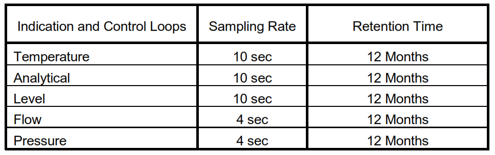
7.10.4 As a minimum, the system shall be designed to ensure capacity mentioned in Table I
7.10.5 If indicated in the project requirement, it shall be possible to historize and to retain trends of 1 sec sampling rate, for mentioned number of tags and retention time.
Table I – Trend Sampling and Retention Time
7.11 Management Information System MIS/PIMS
Refer to SES-X01-E01 for descriptions and details.
7.12 Reports and Logs
7.12.1 The report function shall allow the user to define fixed or free format logs, define periodic execution and to select the output device.
7.12.2 The fixed format reports shall cover current and historical data and display the information on any EWS and OWS.
7.12.3 It shall be possible to define the output device, e.g. printer, or display, or storage media.
7.12.4 The system shall provide the basic types of reports as a minimum to cover operator actions, engineering and system events.
7.12.5 The reports shall be able to use real time, historical, trend, or calculated data generated or stored on any node in the system or in any third party device connected to the system.
7.12.6 The report types shall be:
a. On demand
b. At a predefined time e.g. hourly, shift, daily, etc.
c. Event triggered
d. Historical events to help in diagnosing shutdown incidents. These reports shall be stored on separate files from historical and trend data.
7.12.7 Logging functions shall be able to be initiated by the operator on demand, or on a predefined schedule.
7.12.8 All points in the system shall be available for logging.
7.12.9 A logging report function shall be available on the operator workstation to enable the engineer to make free-format reports of text and data that may be printed on a printer connected to the operator workstation.
8. System Performance
8.1 System Availability
8.1.1 The DCS, in a redundant controller configuration, shall have an availability requirement of 99.99 percent when an MTTR of less than 8 hours is assumed.
8.1.2 Single point component failure shall not result in loss of availability and degradation in functionality and performance of the control system.
8.2 System Reliability
Vendor shall provide a listing of all failure modes of the DCS and the impact of such failure on the system performance. The MTBF numbers for the overall system and critical modules shall be provided.
8.3 System Degradation
System degradation is a condition caused when one or more of the established performance parameters fall outside predetermined limits, resulting in a lowering of system quality of service. The vendor shall provide for graceful degradation such that the system continues to operate in a degraded mode rather than failing completely.
9. Documentation, FAT, and SAT
Refer to SES-X01-E01 for descriptions and details.