Doble Test on Insulations – Power Transformer Diagnostics
Doble testing is important to determine the condition of a transformer, because it can detect winding and bushing insulation integrity and problems in the winding and core. Doble tests are conducted in the field on de-energized transformers using special test equipment. The testing software automatically performs analysis of test results and responds with a four letter code as shown in table 10.

Insulation Power Factor Test
The purpose of this test is to determine the state of dryness of the windings and insulation system and to determine a power factor for the overall insulation, including bushings, oil, and windings. It is a measure of the ratio of the power (I2R) losses to the volt-amperes applied during the test. The power factor obtained is a measure of watts lost in the total transformer insulation system including the bushings. The power factor should not exceed 0.5% at 20°C.
Temperature correction of test results can be done automatically on the Doble test set. The values obtained at each test are compared to previous tests and baseline factory tests, and a trend can be established as the insulation system ages.
Capacitance Tests
This test measures and records the capacitance (including bushings) between the high and low voltage windings, between the high voltage winding and the tank (ground), and between the low voltage winding and the tank (ground). Changes in these values as the transformer ages and events occur, such as nearby lightning strikes or through faults, indicate winding deformation and structural problems such as displaced wedging and winding support.
Excitation Current Test
The purpose of this test is to detect short-circuited turns, poor electrical connections, core de-laminations, core lamination shorts, tap changer problems, and other possible core and winding problems. On three-phase transformers, results are also compared between phases. This test measures current needed to magnetize the core and generate the magnetic field in the windings.
Doble software only gives two indications on this test; one is “G” for good and “Q” for
questionable. On a three-phase, wye/delta or delta/wye transformer test, the excitation current pattern will be two phases higher than the remaining phase. Compare the two higher currents only.
Commentary Note:
Perform the excitation test before any direct current (dc) tests. Excitation Current Tests should never be conducted after a dc test has been performed on the transformer. Results will be incorrect because of residual magnetism of the core left from the dc tests.

In general, if there is an internal problem, these differences will be greater. When this happens, other tests possibly will also show abnormalities, and an internal inspection should be considered. The results, as with all others, should be compared with factory and prior field tests.
Bushing Tests
For bushings that have a potential tap, both the capacitance between the top of the bushing and the bottom tap (normally called C1) and the capacitance between the tap and ground (normally called C2) are measured. To determine bushing losses, power factor tests are also performed. C2 capacitance is much greater than C1. Bushings without a potential tap are normally tested from the bushing top conductor to ground.
These test results shall be compared with factory tests and/or prior tests to determine deterioration. About 90% of bushing failures may be attributed to moisture ingress evidenced by an increasing power factor from Doble testing on a scheduled basis.
Percent Impedance / Leakage Reactance Test
This is normally an acceptance test to see that nameplate percent impedance agrees with the measured percent impedance when the transformer arrives onsite. Normally, a 3% difference is considered acceptable. However, after the initial benchmark test, the percent impedance should not vary more than 2% from benchmark. As the transformer ages or suffers events such as through faults, nearby lightning strikes, and other surges, this test is used in the field to
detect winding deformation. Winding deformation can lead to immediate transformer failure after a severe through fault, or a small deformation can lead to a failure years later.
Changes in leakage reactance and in capacitance tests (explained above), serve as an excellent indicator of winding movement and structural problems (e.g., displaced wedging). This test does not replace excitation current tests or capacitance tests, but complement them and they are used together. The excitation current test relies on reluctance of the core while the leakage reactance test relies on reluctance of the spaces.
Sweep Frequency Response Analysis (SFRA) Test
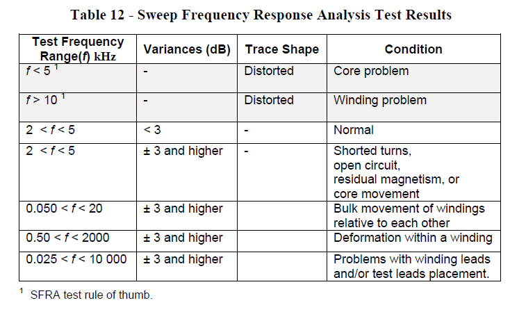
These tests show, in trace form, the winding transfer function of the transformer and are valuable to determine if any damage has occurred during shipping or during a through fault. Core grounds, core displacement, and other core and winding problems can be revealed by this test.
These tests should be conducted before and after the transformer has been moved or after experiencing a through fault. Results should be compared to baseline tests performed at the factory or as soon as possible after receiving the transformer.
Commentary Note:
SFRA should be performed at the transformer manufacturer factory; SFRA should be conducted as an acceptance test to establish a baseline. A baseline should be established for older in service transformers.
For a delta/wye transformer, a test voltage of variable frequency, normally 20 Hz to 2 MHz, is placed across each phase of the high voltage winding. The SFRA sets of tests are as follows:
Test Set 1: Low voltage windings are isolated with no connections on any of the bushings.
Test Set 2: Short-circuiting all the low voltage windings and again placing the test voltage on each phase of the high voltage winding.
Test Set 3: Isolating the high voltage winding and placing the test voltage across each low voltage winding.
