Infrared Temperature Analysis – Power Transformer Diagnostics
Infrared analysis should be conducted while equipment is energized and under full load,
if possible. IR analysis is preferably conducted after any maintenance or testing. Also,
if IR is done during factory heat run, the results can be used as a baseline for later
comparison.
Infrared IR for Transformer Tanks
Unusually high external temperatures or unusual thermal patterns of transformer tanks indicate problems inside the transformer such as low oil level, circulating stray currents, blocked cooling, loose shields, or tap changer problems. Infrared scanning and analysis is required for trending purposes by NFPA 70B, Recommended Practice for Electrical Equipment Maintenance and IEEE 62.
Abnormally high temperatures can damage or destroy transformer insulation and, thus, reduce life expectancy. Thermal patterns of transformer tanks and radiators should be cooler at the bottom and gradually warmer ascending to the top. Figure 3 shows a normal pattern; the red spot at the top is normal showing a “hot spot” top of B phase about 110°F. Any departure from this pattern means a probable problem which must be investigated. An IR inspection can find overheating conditions or incorrect thermal patterns.

Figure 3: Normal Transformer IR Pattern
Infrared IR for Surge Arresters
Surge arresters should be included when infrared scanning energized transformers. Look for unusual thermal patterns on the surface of lightning arresters. Figure 4 shows arrester IR image. The yellow in the top right of the image is a reflection not associated with the arrester. A temperature profile of the arrester is shown as black lines. Note the hot spot (yellow) about a third of the way down from the top. This indicates that immediate de-energization and replacement must be undertaken. Catastrophic failure is imminent which can destroy nearby equipment and be hazardous to workers. Also, compare thermal
patterns to identical units or earlier scans of the same arrester. Scan all high voltage connections and compare them to nearby connections for unusual temperatures.

Infrared IR for Bushings
IR scans of bushings can show low oil levels which would call for immediate deenergization and replacement. This generally means:
• The seal in the bushing bottom has failed,
• Leaking oil into the transformer,
• The top seal has probably failed also allowing air and moisture to enter the
top.
Too high an oil level in a bushing generally means:
• The seal in the bottom of the bushing has failed,
• Oil head from the conservator, or nitrogen pressure, has pushed transformer oil up the bushing.
• Top seal leaking, allowing water to enter. The water migrates to the bushing bottom displacing the oil upward.
Over 90% of bushing failures are attributed to water entrance through the top seal. Bushings commonly fail catastrophically, many times destroying the host transformer or breaker and nearby equipment and causing hazards to workers. Figure 5 shows low oil level in a high voltage transformer bushing. Compare previous IR scans of the same bushing with the current scan.
Hot-collar tests are effective in locating cracks in porcelain, deterioration or contamination of insulation in the upper section of a bushing, low compound or liquid level, or voids in compound. However, Doble tests are run infrequently, and the transformer has to be out of service, under clearance, and both primary and secondary conductors removed, while an IR scan can be easily done at any time.
Infrared IR for Radiators and Cooling Systems
Figure 6 shows IR image with a cold left radiator section plugged. If visual inspection shows the valves are open, the radiator or segment must be isolated, drained, and removed and the blockage cleared. Operating a transformer with reduced cooling drastically shortens transformer life. An increased operating temperature of only 8 to 10°C may reduce transformer life by one-half. IR scans all cooling systems, including heat exchangers, fans, pumps, motors, etc. IR could be used to check inside control panels for overloaded wiring, loose connections, and overheated relays. Unusual thermal patterns shall be reported
and compared with similar equipment.
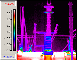
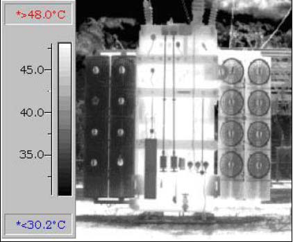
Figure 6: IR Image Showing Blocked Radiators
Corona Scope Scan – Power Transformer Diagnostics
With the transformer energized, bushings and surge arresters scan should be scanned for
unusual corona patterns. Corona should be visible only at the top of bushings and arresters, and corona at connections should be similar to identical connections. As a bushing deteriorates due to physical defects, the corona pattern will grow progressively larger. When the corona pattern reaches a grounded surface (i.e., the tank or structure), a flashover will occur destroying the bushing or arrester and perhaps the transformer. The corona scope will reveal this problem long before a flashover.