1. SCOPE ………………………………………………………………………..2. REFERENCE DOCUMENTS
3. DEFINITIONS
4. GENERAL ……………………………………………………………………4.1
Response Spectra Method
4.2
Damping
Values
4.3
Computer Model ……………………………………………………….
4.4 Vibration Control
4.5
Hydraulic and Rotary Snubbers
FIGURE
1 Horizontal Design Response, Horizontal Ground Acceleration2 Vertical Design Response, Horizontal Ground Acceleration
TABLE
I Damping
Values
II
Horizontal Design Response Spectra Relative Values of
Spectrum Amplification Factors for Control Points ……………..III Vertical Design Response Spectra Relative Values
of Spectrum Amplification Factors for Control Points
1. Scope
This standard establishes design requirements for piping systems subject to the dynamic effects of
seismic loads and supplements the requirements for ASME B31.1, ASME B31.3, ASME B31.4, and ASME
B31.8.
2. Reference Documents
Reference is made in this standard to the following documents. The latest issues, amendments, and
supplements to these documents shall apply unless otherwise indicated.
SABIC Engineering Standards (SES)
P01-E01 Design Conditions and Basis for Pressure Piping
P01-E02 Design of Piping Systems for Stress and Pressure Criteria
P01-E03 Flexibility, Support, and Anchoring of Piping systems
American Society Of Mechanical Engineers (ASME)
Sect III Division 1 Rules for Construction of Nuclear Power Plant Components, Non-Mandatory
Appendices, Appendix N Dynamic Analysis Methods
Sect III Division 1 Rules for Construction of Nuclear Power Plant Components, Subsection NF,
Component Supports
U.S. Regulatory Commission (NRC)
Regulatory Guide 1.61 – Design Response Spectra for Seismic Design of Nuclear Power Plants
Regulatory Guide 1.92 – Combining Modal Responses and Spatial Components in Seismic Response
Analysis
3. Definitions
Closely Spaced Modes. Two consecutive modes are considered closely spaced if their frequencies differ
from each other by 10% or less of the lower frequency.
Response Spectrum. A plot giving the maximum responses in terms of displacement, stress, or
acceleration, of all possible linear one degree systems due to a given input of ground motion. Usually
plotted with the abscissa of the spectrum as the natural frequency or period of the system and the ordinate
as the maximum response in terms of displacement, stress, or acceleration.
Earthquake Response Spectrum. An empirical response spectrum computed for a particular
earthquake. When combined with other earthquake spectra, it can be used to estimate a proper spectrum
for general design purposes, known as a design response spectrum.
Operating Basis Earthquake. An earthquake which, considering the regional and local geology and
seismology and specific characteristics of local subsurface material, could reasonably be expected to
affect the plant site during the operating life of the plant. It is that earthquake which produces the vibratory
ground motion for which those features of the plant necessary for continued operation without undue risk
to the health and safety of the public are designed to remain functional. Usually considered as having a
much higher probability of occurrence, possibly with a ‘return period’ period of the order of 100 to 200
years, and an intensity which is often taken as half of that of a Safe Shutdown Earthquake. The design is
made at somewhat lower allowable stresses and for somewhat different combinations of conditions.
Owner. SABIC.
Safe Shutdown Earthquake. An earthquake which is based upon an evaluation of the maximum
earthquake potential considering the regional and local geology and seismology and specific
characteristics of local subsurface material. It is that earthquake which produces the maximum vibratory
ground motion for which certain structures, systems, and components are designed to remain functional.
Usually considered a “maximum credible earthquake”, which has only a small probability of occurrence
during the lifetime of the plant, and for which the design is made at yield levels or limit conditions.
Zero Period Acceleration (ZPA). The maximum ground acceleration which corresponds to zero period in
the design response spectra for the site.
4. General
The decision and methodology of using dynamic analysis in piping systems for earthquake applications
shall reside with the Owner’s engineer. Current software programs exist that possess varying capabilities
for performing seismic dynamic analysis. The use of both commercial and proprietary software for
performing seismic dynamic analysis shall be subject to review and approval by the Owner’s engineer.
Dynamic analysis procedures, when used, shall be based on an appropriate ground motion representation,
shall be performed using accepted principles of dynamics, and conform to the criteria applied in this
standard.
4.1 Response Spectra Method
The response spectra method is a dynamic analysis procedure that utilizes the ordinates of a Design
Response Spectra (derived from records of past strong-motion earthquakes) to calculate the peak modal
responses which correspond to the modal periods of the piping system. Only those modes having a
significant contribution to the total piping system response are utilized. The maximum modal contributions
are combined in a statistical manner to obtain an approximate total response of the piping system.
4.1.1 The design response spectra shall be based on the geologic, tectonic, seismologic, and soil
characteristics associated with the specific site. Response spectra, derived from ground motion time
histories developed for the specific site, either individually or in combination, shall be representative of
actual earthquake motions and shall approximate the design response spectra. Design response spectra
developed from site specific data shall be utilized only with the approval from the Owner’s engineer.
4.1.2 In order to ensure that only those vibratory modes of a piping system that have a significant
contribution to the total piping system response are utilized, at least 90% of the participating mass of the
piping system shall be included in the calculation of response in each principal horizontal direction.
4.1.3 The procedure for developing a design response spectra shall follow the requirements set forth in
NRC Regulatory Guide 1.60, Design Response Spectra for Seismic Design of Nuclear Power Plants.
4.1.4 The design response spectra used for a dynamic seismic analysis shall represent the effects of the
vibratory motion of a Safe Shutdown Earthquake (SSE), ½ the Safe Shutdown Earthquake, and the
Operating Basis Earthquake (OBE).
4.1.5 The response spectra method for an earthquake analysis shall consider the representative maximum
values of the piping system response to each of the three components of earthquake motion, namely in the
horizontal (x and z) and vertical (y) directions. The modal responses may be combined in accordance with
the methods outlined in NRC Regulatory Guide 1.92, Combining Modal responses and Spatial
Components in Seismic Response Analysis and shall consist of either the Square Root Sum of the
Squares Method(SRSS) for closely spaced modes, or other choices such as the Group Method, Double
Sum Method, or the 10% Method shall be subject to review by the Owner’s engineer
4.2 Damping Values
Damping values to be utilized in the design of a Safe Shutdown Earthquake and Operating Basis
Earthquake shall be in accordance with ASME Sect III Div 1, Appendix N, Table N-1230-1 (Attachment 1.)
4.3 Computer Model
4.3.1 The computer model of a physical piping system shall represent the spatial distribution of the mass
and stiffness of the piping system to the extent that it is adequate for the calculation of the significant
parameters of its dynamic response. For computer programs which utilize the lumped mass method, half
the mass between two support points is lumped at each support node when node points are located only at
support points. In order to evaluate the vertical component of an earthquake and ensure a more accurate
mass distribution, at least one additional intermediate node point shall be placed at midspan between
supports. For bends, nodes shall be placed at initial, middle, and final locations of the bend.
4.3.2 The computer model of the piping system shall include the support structure of the piping, together
with its mass and damping characteristics. See 4.3.5 below.
4.3.3 The cut off frequency to be used in the response spectra method analysis shall be obtained by using
the frequency projected from the ground acceleration of the design response spectra. In most cases, this
value will be approximately equal to 33 hz. This will increase the likelihood that most of the lower
“amplified” modes which contribute to the bending behavior of the piping system’s response will be
captured.
4.3.4 If the piping system can withstand the maximum acceleration in the design response spectra applied
in any direction, a static seismic analysis shall be considered a sufficient method of analysis.
4.3.5 For piping systems supported from both the ground and from buildings, spectra for both ground and
building shall be developed to account for independent support motion. The range of support nodes
corresponding to each particular shock spectra must be specified.
4.3.6 A visual inspection of the design response spectra shall be made for the purposes of determining
which frictional supports can be considered restraints:
a. The frequency at which the spectral acceleration is less than the coefficient of friction at the
supports in the piping system shall be determined.
b. The natural frequency calculated at the supports from the modal analysis shall be compared to
the frequency in 4.3.6 a).
c.
If the natural frequency calculated at the supports is less than the frequency determined in 4.3.6
a), the frictional resistance will be overcome and a restraint may be required to dampen the system.
d.
If the natural frequency calculated at the supports is greater than the frequency calculated in
4.3.6 a), then the frictional resistance at the support may be treated as a restraint.
4.4 Vibration Control
4.4.1 Vibration due to seismic disturbances may be controlled by the use of a variety of restraints such as
anchors, guides, hold down clamps, rigid struts, sway braces, and hydraulic and mechanical snubbers.
4.4.2 Restraints that require periodic maintenance, such as hydraulic snubbers, shall be located whenever
possible, near platforms for accessibility.
4.5 Hydraulic and Rotary Snubbers
4.5.1 Hydraulic and rotary snubbers shall conform to the requirements established in MSS SP-58 – Pipe
Hangers and Supports – Materials, Design and Manufacturer and ASME Section III, Subsection NF.
4.5.2 Care shall be taken to ensure hydraulic snubbers are installed with reservoir breather filters on top,
reservoirs filled to the proper level, and piston setting set to the required cold piston setting.
TABLE I
Damping Values
Percent of Critical Damping
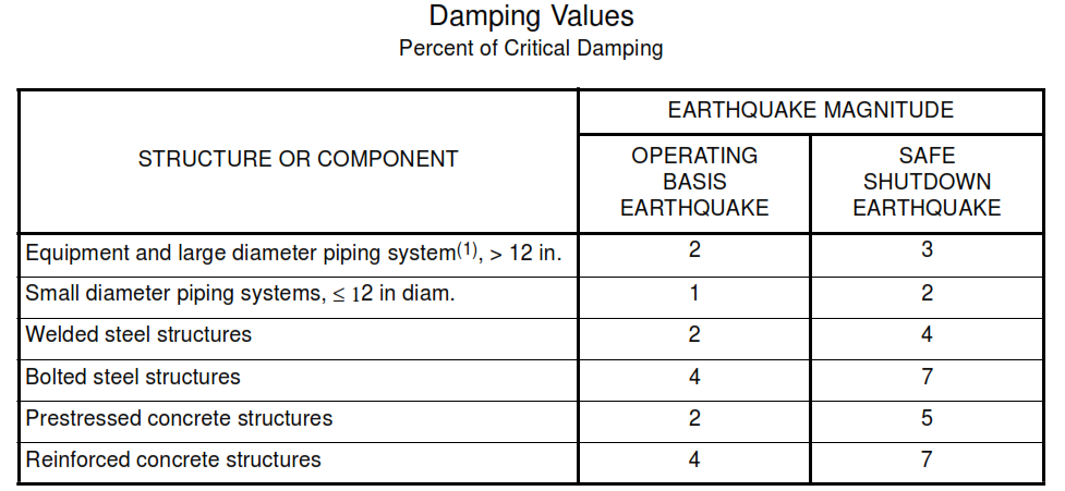
(1)
Included both material and structural damping. If the piping system consists of only one or two spans,
with little structural damping, use values for small diameter piping.
TABLE II
Horizontal Design Response Spectra Relative Values of
Spectrum Amplification Factors for Control Points
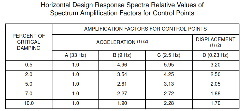
(1)
Maximum ground displacement is taken proportional to maximum ground acceleration and is 36 in
for ground acceleration of 1.0 g.
(2)
Acceleration and displacement amplification factors are taken from recommendations given in
Ref, 1 and discussed in Refs. 2 and 3.
TABLE III
Vertical Design Response Spectra Relative Values
of Spectrum Amplification Factors for Control Points
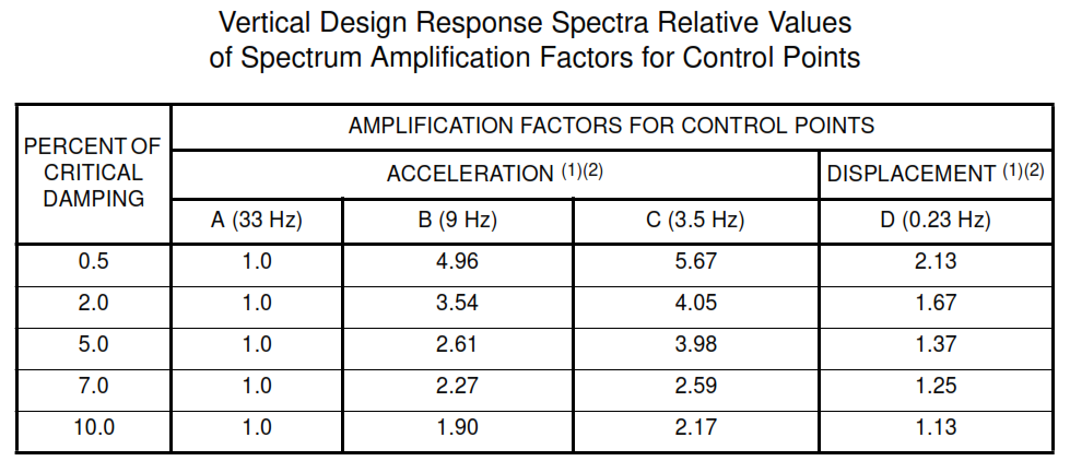
(1)
Maximum ground displacement is taken proportional to maximum ground acceleration and is 36
in for ground acceleration of 1.0g.
(2)
Acceleration amplification factors for the vertical design response spectra are equal to those for
horizontal design response spectra at a given frequency, where displacement amplification
factors are 2/3 those for horizontal design response spectra. These ratios between the
amplification factors for the two design response spectra are in agreement with those
recommended in Ref. 1 and discussed in Refs. 2 and 3.
FIGURE 1
Horizontal Design Response, Horizontal Ground Acceleration
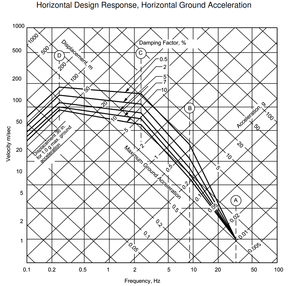
FIGURE 2
Vertical Design Response, Horizontal Ground Acceleration
