Testing of EHV/HV GIS (Extra High Voltage/High Voltage Gas Insulated Switchgear) circuit breakers is a critical aspect of ensuring their reliability, performance, and compliance with industry standards. Various tests are conducted during the manufacturing, commissioning, and maintenance phases to verify the proper functioning of GIS circuit breakers.
TEST EQUIPMENTS: Megger IR test Kit, Contact Resistance Test Kit, Circuit Breaker Analyzer.
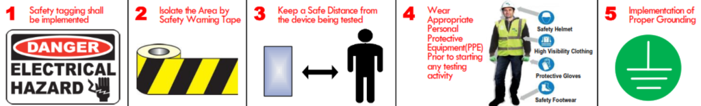
SAFETY PRECAUTIONS – The following Safety precautions shall be taken in consideration prior, during and after conducting the test measurements.
- Safety tagging shall be implemented.
- Isolate the Area by Safety Warning Tape.
- Keep a Safe Distance from the device being tested.
- Wear Appropriate Personal Protective Equipment(PPE) Prior to starting any testing activity.
- Implementation of Proper Grounding.
EHV/HV GIS Circuit Breaker Test Procedure
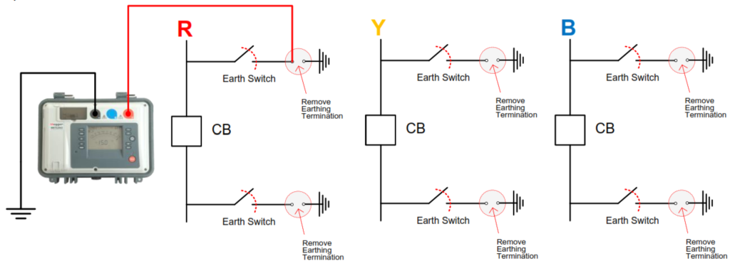
Perform the Insulation Resistance test.
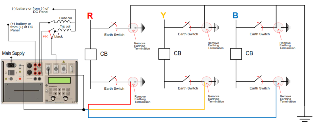
1.1 Remove the Earthing Wire Termination as shown in the below diagram.
1.2 Closed the associated Earth Switches of each the Circuit Breaker’ phases.
1.3 Inject 5kV DC for 1 minute as per the following Phase to ground test connection diagram and repeat for the remaining
phases Y and B.
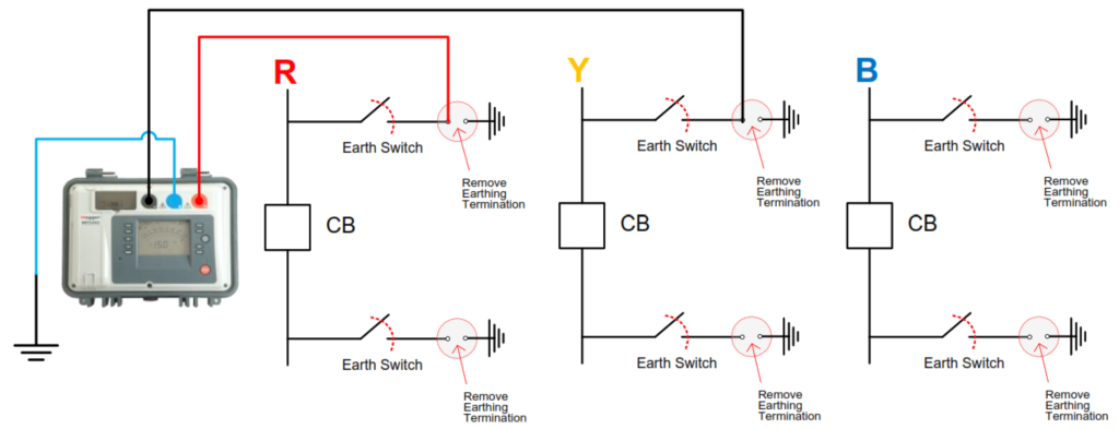
1.4 Repeat the Test for phase to phase (R to Y, Y to B and R to B) connection as per the the following diagram:
1.5 Record the measured values in the applicable test forms and evaluate as per acceptable standards/criteria (>100 MΩ ).
Perform the Contact Resistance test.
2.1 Remove the Earhing Wire Termination as shown in the below diagram.
2.2 Closed the associated Earth Switches of each the Circuit Breaker’ phases.
2.3 Inject 100A DC for 1 minute as per the following test connection diagram and repeat for the remaining phases Y and B.
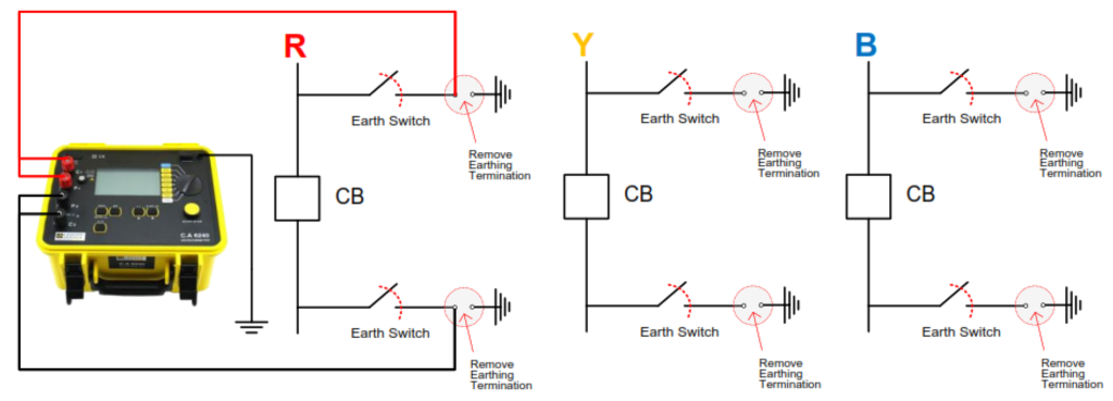
2.4 Record the measured Voltage Drop.
2.5 Record the measured resistances in the applicable test forms and evaluate as per acceptable standards/criteria: (< 300 microΩ).
3. Perform the OPEN and CLOSE Timing test as per the following Test connection diagram.
3.1 Print Record the measured values in the applicable test forms and evaluate as per acceptable standards/criteria (< 20 msec).
4. Circuit Breaker Anti-Pump Relay Function verification test
Verify the anti-pump function after closing the circuit breaker electrically by maintaining the close signal and observing that the close circuit has an open contact in the circuit, preventing further
close operations as long as the close signal is maintained. This prevents the circuit breaker from
trying to close immediately after being tripped open (pumping) on concurrent close and trip
signals. The Anti-Pump Relay (Y-Relay) prevents the circuit breaker from trying to close immediately after being tripped open.
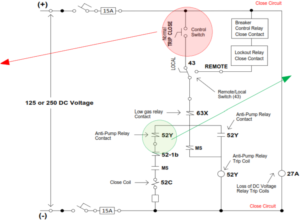
When an electrical closing command is issued, only a single closing operation results. The antipump
relay is energized when the close signal is applied. The anti-pump relay, when sealed in, opens a
contact in the close circuit.