1. PURPOSE – This Electrical engineering article defines design criteria used for electric heating under cryogenic equipment foundations to prevent upheaval caused by the formation of ice in the underlying soil strata.

2. Electric Heating for Cryogenic Equipment Foundations
This article applies to the design of electric heating for soil-bearing foundations supporting cryogenic equipment such as liquid nitrogen (LIN), liquid oxygen (LOX), and liquid argon
(LAR) flat bottom storage tanks and field-erected cold boxes. This standard does not apply to pile-supported foundations that provide an air circulation space between the bottom of the
foundation and the soil, or for shop-fabricated cold boxes that provide an air circulation space between the cold equipment and the top of concrete, as described in 3CS02004.
3. RELATED DOCUMENTS
3.1 ngineering Articles
3CS02004 Frost Heaving Prevention of Cryogenic Equipment Foundations
3.2 Electrical Installation Standard Detail Drawings
STAC Drawing number: Standard ELEC 0002
Detail T11 Cold Box Foundation
Detail T12 Typical One Line Diagram
Detail T13 Control Panel Layout and Termination Detail
4. HEATING REQUIREMENTS
- The power (wattage) requirements are based on the assumptions that the heater is on 50% of the time, and the heater is turned on and off when the controlling Resistance Temperature Detector (RTD) reaches 3°C and 7°C.
- All conduit spacing dimensions in this document refer to centreline of conduit.
- LOX, LIN, and LAR Storage Tanks
- This is applicable to flat bottom storage tanks with a minimum of 500 mm high foam glass insulation under the inner tank. This requirement applies to the slab foundation with or without the haunch and the ring-wall foundation.
- The heating cable shall be designed for 48 watts per square metre. This requirement may be transformed into the following heater spacing-wattage requirement:
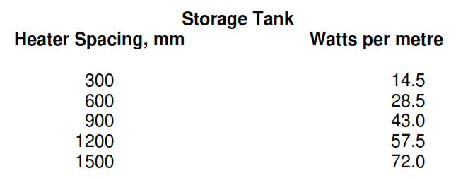
Note: The maximum heater spacing shall not exceed 1500 mm. The active heated length of the cable shall extend a minimum of 600 mm beyond the inner tank anchor bolt circle on each
side.
4.4 Column Cold Box
4.4.1 The amount of heat required under the column cold box is 66 watts per square metre, which may be related to the heater spacing-wattage requirement as shown below:

Note: The maximum heater spacing shall not exceed 900 mm.
4.5 Non-column Cold Box
4.5.1 The amount of heat required under the non-column region of the cold box is 37 watts per square metre, which may be related to the heater spacing-wattage requirement as shown
below:
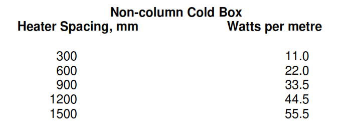
Note: The maximum heater spacing shall not exceed 1500 mm.
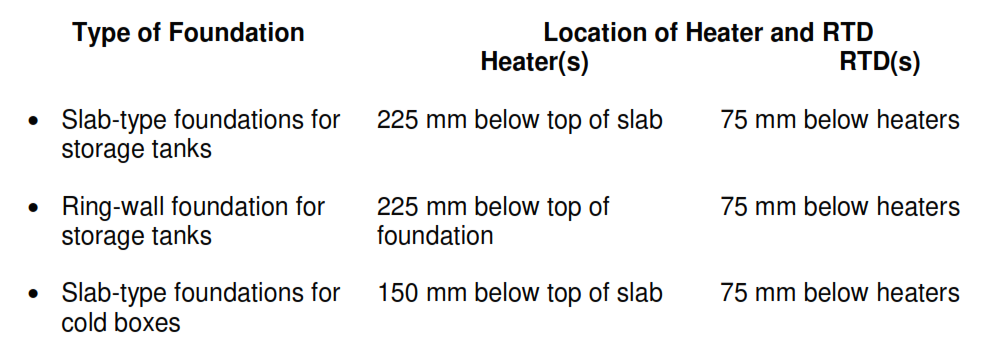
5. HEATER AND RTD LOCATION
The location of the heater and RTD shall be as specified in the following tabulation:
Note: All dimensions are to centerline of conduit.
6. HEATING CABLE
Cable shall be the series resistance type preformed to provide a constant output per length or of the parallel resistance type, having a series of heating zones which produce a constant
output per unit length. The types of cables with the construction that is suitable for Company installation practice are manufactured by the following companies:
• Series Resistance Type
BICC General Pyrotenax Cables Ltd (Thermoheat Division)
Hedgeley Road, Hebburn, Tyne & Wear NE31 1XR, United Kingdom.
• Parallel Resistance Type
Raychem: Tyco Thermal Controls (UK) Ltd
3 Rutherford Road, Stephenson Industrial Estate, Washington
Tyne & Wear. NE37 3HX United Kingdom
Thermon (U.K.) Ltd.
7th Avenue, Team Valley Trading Estate, Gateshead
Tyne & Wear. NE11 0JW United Kingdom
As a minimum, the heating cable selected shall provide the watts per metre listed in the heating requirements. No single heating cable circuit length shall exceed 60 m.
7. SYSTEM CONTROL AND EQUIPMENT
1 The electrical designer shall confer with the project engineer and process controls engineer to determine the exact method of foundation heat tracing control to be used for a particular
project.
2 For control of foundation heat tracing, the following controller system shall be used.
-
- Enclosure shall be made of sheet steel construction and shall be provided with a weather protection canopy suitable for outdoor use (IP 55 minimum), and shall include steel frame for fixing to concrete slab. Enclosure will house temperature controller, override switch, incoming rotary isolator, Contactor, Residual Current Circuit Breaker (RCCB)/Moulded Case Circuit Breaker (MCBs), linked/fused terminals (as required), and circuit indicator lamps. Heater system on/off indication shall be provided, and supply cables and heater/sensor tails shall enter from below. An undrilled, removable gland plate shall be provided at the base of the panel.
- The Temperature Indicating Controller type and model shall be subject to approval by Company prior to manufacture; the vendor shall include full technical details with his bid.
The output switch shall close contacts at 3°C decreasing and not open until 7°C increasing. An alarm output contact to the DCS system shall be initiated at 1°C.
3 Junction Boxes
Junction boxes shall be made of stainless steel construction with ingress protection to IP 65 minimum. Junction boxes shall be supplied with all necessary gland entries predrilled. Gland
entries shall be provided with removable plugs size (M20 x 1.5), suitable for maintenance of ingress protection prior to cable installation.
8. HEATING CABLE INSTALLATION
Heating Cable shall be installed in 20 mm (3/4 in) conduit (rigid galvanized steel) located in accordance with the tabulation specified in paragraph (HEATER AND RTD LOCATION). All conduit ends shall be tapped and plugged.
- PT100 RTDs shall be installed in 20 mm (3/4 in) conduit (rigid galvanized steel) located at elevation specified in paragraph 5.1. All conduit ends shall be tapped and plugged.
- Storage Tanks. Two RTDs shall be installed per tank. The conduit shall run perpendicular to the heating cables at the tank’s equator. One RTD shall be located as near as possible to the tank’s centre and the other beneath the inner tank’s tie-down straps or anchor bolts, and each RTD shall be equidistant from the two adjacent heating cables.
- The RTD nearest the tank’s centre shall be connected to the control system. (The purpose of the other RTD is for investigating and locating leaks if indications of ice formation appear.)
- Cold Boxes. One RTD shall be installed at the centre of the column and equidistant from the two adjacent heating cables. The conduit shall run under the centreline of the column parallel to the heating cables.
IEC Electrical Trace Heating Installation in Process Plants