ELECTRICAL COMMUNICATION SYSTEM PROCEDURE
- All permanent materials (including fabricated supports), consumables, construction area and resources shall be prepared and checked prior to installation works.
- Ensure that all Electrical Equipment and materials, which would suffer damage or deterioration from exposure to the elements has been properly stored indoor, off the ground in suitable warehousing.
- Materials and equipment to be installed shall be inspected to ensure the conditions. Should there be factory and handling damages found in the equipment and/or materials, Subcontractor shall record to QC Material Receiving Inspection report form and immediately inform EPC for disposition.
- Ensure that working areas are ready for installation of electrical equipment, properly turned over to Subcontractor Electrical Department by Building subcontractor with a duly accomplished Work Transfer Sheet.
- All equipment foundation, base plates, cable entries, oil pits and firewalls (if any) shall be checked for its line and grade against actual dimension of the equipment. Foundation of particular equipment shall be checked to include stub-up prior to acceptance of work transfer sheet. Surveyor shall verify the elevation of the equipment and to be incorporated in the “AS-BUILT” drawings. Any deviations found against AFC drawings, shall be brought to the attention of Company.
- Work Transfer Sheet shall be duly signed and processed by other subcontractors or discipline for the preceding works to avoid confusion and discrepancies in the work responsibilities.
- Architectural finishing works of the building (needed for selected activities) shall have been completed; in particular, room ventilation, temperature, and humidity level shall be within the limits recommended by the equipment vendor. Indoor equipment to be installed in the building shall be maintained at required room temperature.
- Review all references such as the latest Approved for Construction (AFC) drawings, layout, and technical scope of work, work permit requirements, and work procedures including safety standard requirements.
- Equipment that has been shipped in sections and/or has loose components shall be identified and checked with corresponding equipment package lists.
- Equipment tags shall be identified and scheduled with respect to the latest issued Approved for Construction drawings as well as to the approved milestones schedules.
PAGING SYSTEM INSTALLATION
- Survey and study the designed location of paging system
- Check locations and provide markings to which elevations, mounting height and orientations should conform in the latest issued Approved for Construction drawings.
- Install necessary fabricated supports as required per installation detail. Ensure that the orientation shall comply with the drawing layout.
- Verify the installed support against equipment to be installed if suited as per requirements of EPC technical scope of works and latest issued Approved for Construction drawing.
- All cabinets shall be correctly leveled and aligned before fastening to the support as per Saudi Aramco specification.
- Prior to installation of cable tray underneath tile flooring at Communication room the following item shall be considered.
- Base plate of cable tray supports shall be anchored at the floor through expansion bolt floor drilling at communication.
- Align the cable tray supports and ensure that tray routes are accessible starting from end of trench to building cable entry.
7. Cable tray installation shall be underneath floor tiles at communication room. Complete with fittings and accessories as per requirement.
8. Installation of grounding bus bar to accommodate the possibility of excessed number of grounding cable to be connected from different communication boxes based on the detailed approved for construction drawing.
9. Provide grounding bonding for supports and trays connected to grounding bus bar.
10. QC shall inspect, accept or reject installed cabinet rack and cable tray support.
MAIN AMPLIFIER CABINET INSTALLATION (INDOOR)
- Survey and study the designed location of main amplifier cabinet.
- Check locations and provide markings to which elevations, mounting height and orientations should conform in the latest issued Approved for Construction Drawings.
- Fabricate and install cabinet rack for Main Amplifier cabinet at communication room.
- Unload the main amplifier cabinet by utilizing crane equipment.
- Uncrate the main amplifier cabinet before moving to communication room.
- Pallet truck should have been ready for bringing amplifier cabinet inside the communication room.
- All cabinets shall be correctly leveled and aligned before fastening to the support as per Saudi Aramco specification.
- Provide grounding bonding for supports and trays connected to grounding bus bar.
- QC shall inspect, accept or reject installed cabinet rack and cable tray support.
LOCAL AMPLIFIER JUNCTION BOX (INDOOR, WALL MOUNTED)
- Check relevant drawing regarding the detailed installation and exact location of local amplifier Junction boxes inside the building.
- Check locations and provide markings to which elevations, mounting height and orientations should conform in the latest issued Approved for Construction drawings.
- Install necessary fabricated supports as required per installation detail. Ensure that the orientation shall comply with the drawing layout. Proper measurements, concrete wall drilling to fix the supports by using expansion bolt if no indication of embedded steel materials on the wall.
- Install local amplifier junction box with complete fittings and accessories. This will serve as mock up installation for approval.
- Provide earth bonding between junction boxes and trays as well as conduits and shall be connected to the allocated grounding bus bar.
- For touch up painting for every steel surface, edging caused by cutting, drilling, welding and grinding, refer to project Spec.
- QC shall inspect the completed activity for junction box and cable tray. Mock up installation inspection result shall be recorded using appropriate and approved forms reflected on SATIP.
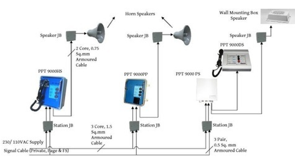
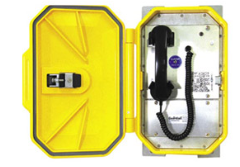
PARTY PAGE STATION INSTALLATION (INDOOR, WALL MOUNTED)
- Survey and study the designed location of party page station, junction box, and speaker in the building.
- Install necessary fabricated supports for party page station, junction box, speaker and conduits. Angular and C-channel are to be used for support as per relevant approved for construction drawing.
- Ensure proper measurements for concrete wall drilling to fix the supports by using expansion bolt if no indication of embedded steel materials on the wall for mounting the supports.
- Installation of party page station, junction box and speaker with its fittings and accessories, conduits and conduit fittings shall be in accordance with latest approved for construction drawing. This will serve as a mock up installation for approval.
- Provide earth bonding between junction boxes and trays as well as conduits and shall be connected to the allocated grounding bus bar.
- Ensure proper use of glands prior to cable termination between junction box, party page station, and speaker. Install proper lugs with core marker and cable tags as per requirements.
- The terminator should have with them a termination schedule prior to start of the activities to avoid confusion and disorientation of junction box, party page station and speaker.
- QC shall inspect the completed activity for handset, junction box, speaker and cable tray. Mock-up installation inspection result and recorded using appropriate and approved forms reflected on SATIP.
PARTY PAGE STATION INSTALLATION (OUTDOOR, WALL MOUNTED)
- Survey and study the designed location of party page station, junction box and speaker in plant.
- Install necessary fabricated supports for in-plant party page station, junction box and speaker including conduits.
- Installation of party page station, junction box and speaker with its fittings and accessories, conduits and conduit fittings shall be in accordance with latest approved for construction drawing. This will serve as a mock up installation for approval.
- Provide earth bonding between junction boxes and trays as well as conduits and shall be connected to the allocated grounding bus bar.
- For touch up painting for every steel surface, edging caused by cutting, drilling, welding and grinding, refer to project spec.
- Party page station and junction box in plant/underneath pipe rack shall be mounted with supports including cable trays and conduits on structural steel or concrete column, based on the latest issued approved for construction drawing.
- Ensure proper use of glands prior to cable termination between junction box, party page station, and speaker. Install proper lugs with core marker and cable tags as per requirements.
- The terminator should have with them a termination schedule prior to start of the activities to avoid confusion and disorientation of junction box, party page station and speaker.
- QC shall inspect the completed activity for handset, junction box, speaker and cable tray. Mock-up installation inspection result and recorded using appropriate and approved forms reflected on SATIP.
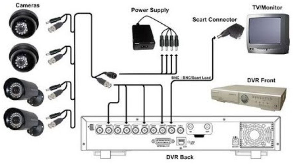
CCTV CENTRAL CABINET INSTALLATION
- Survey and study the designed location of CCTV central cabinet.
- Check locations and provide markings to which elevations, mounting height and orientations should conform in the latest issued Approved for Construction drawings.
- Fabricate and install cabinet rack for CCTV central cabinet at communication room.
- Verify the installed support against equipment to be installed if suited as per requirements of Company technical scope of works and latest Approved for Construction Drawing.
- Prior to installation of cable tray underneath tile flooring at Communication room the following item shall be considered.
- Base plate of cable tray supports shall be anchored at the floor through expansion bolt floor drilling at communication room.
- Align the cable tray supports and ensure that tray routes are accessible starting from end of trench to Central Control Building cable entry.
- Cable tray installation shall be underneath floor tiles at communication room. Complete with fittings and accessories as per requirement.
- CCTV central cabinet shall be in placed to the rack and properly leveled and aligned. Fixing bolt shall be properly tight.
- CCTV monitor, controller, receiver, converter and other accessories shall be installed and aligned according to the latest issued approved for construction drawing.
- Provide earth bonding between junction boxes and trays as well as conduits and shall be connected to the allocated grounding bus bar.
- For touch up painting for every steel surface, edging caused by cutting, drilling, welding and grinding, refer to project spec.
- CCTV central cabinet shall be inspected. QC inspector shall witness the activities. The result shall be recorded using appropriate and approved forms reflected on SATIP.
DESK TOP TYPE OPERATION CONSOLE INSTALLATION (INDOOR)
- Survey and study the designed location of console desk top in the control room.
- Check locations and provide markings to which elevations, mounting height and orientations should conform in the latest issued Approved for Construction drawings.
- Fabrication and installation of support for patch panel shall be as per installation detail. Ensure that the orientation shall comply with the drawing layout.
- Install local junction box/patch panel and conduits, routed from wall to ceiling down to desk top with complete fittings and accessories.
- Install/assemble console desk top and accessories.
- Cable interconnection (patch cord cable), from data Telecommunication panel to patch panel down to console desk top by plugging in the patch.
- QC shall inspect the completed activity for console desktop and patch panel, conduits and patch cord installation. Mock-up installation shall be requested and recorded using appropriate and approved forms reflected on SATIP.
CCTV CAMERA INSTALLATION
- Check locations and provide markings to which elevations, mounting height and orientations should conform in the latest issued Approved for Construction drawings.
- Camera shall be installed, in placed manually taking into consideration all necessary precaution to prevent material damages due to poor handling, lack of information and manual installation
- Support for camera base shall be fabricated and installed as per approved detailed drawing.
- Brackets (vendor supply) for camera shall be available for mounting.
- Enclosure type patch panel junction box shall be installed as per vendor recommendation and latest issued approved for construction
- Supports for conduits shall be fabricated and installed as per site
- Conduits shall be installed as per latest issued approved for construction drawing.
- For touch up painting for every steel surface, edging caused by cutting, drilling, welding and grinding, refer to project spec.
- QC shall inspect the completed activity for CCTV Camera, junction boxes and peripherals installed and its supports. Mock-up installation shall be requested and recorded using appropriate and approved forms reflected on SATIP.
FIBER OPTIC INSTALLATION
- Site plan, cable specifications, drawings and related documents shall be prepared and reviewed with regards to respective areas and tackled all aspects to consider logistic and resources
- For underground cable installation, ensure that trenches are of proper route, width, depth and sand bedding dimensions as shown on approved for construction drawings. Compaction requirement shall be as per Saudi Aramco standard. QC inspection shall be requested and recorded using appropriate and approved forms reflected on SATIP.
- Sand bedding/sand filling materials to be used shall be as per SAES-T-928 of the approved type of cable use and free from any sharp stones, debris and contaminant materials.
- When communication, signal and power cable run in parallel at underground, segregation distance shall be followed and maintained.
- For above ground cable installation, cable tray and conduit shall be free from sharp edges, foreign objects and unnecessary bends. Before installing cables, remove foreign object, burrs and moisture from conduit and equipment enclosures.
- Provide earth bonding between junction boxes and trays as well as conduits and shall be connected to the allocated grounding bus.
- Cable management in-charge shall confirm that the individual cable lengths are taken from the designated cable drums.
- Cable pulling tension and bending radius shall not exceed the limitations recommended by the cable manufacturer. Refer to SAES-T-481Sec. 6 para. 6.11.
- Cable pulling for fiber optic cable shall be conducted manually. It shall be secured and protected from falling objects, debris and should be avoided to cross in the walk way without any cover for
- Prior to fit up of cable glands, check the cable gland schedule to conform to the correct size, type and area classification. Where glands are to be installed in hazardous areas, the certification of the gland shall be verified.
- Before tightening the cable gland ensure that the cable tails are of correct tails and undamaged during stripping, earth is terminated and tagged as required, and the outer sheath of the cable is contained within the gland.
- Fiber optic fibers shall be spliced using fusion splicing equipment or approved mechanical splices. Refer to SAES-T- 624 Sec. 4 sub 4.7.5.
- Terminate all wiring or cable connections according to the wiring diagram, installing all termination requirements including identification required to which non-corroding material with cable reference numbers.

Industry Codes
NFPA 70 National Electrical Code (NEC)
NFPA 72 National Fire Protection Association
TOOLS AND EQUIPMENT
Tools and equipment needed should be in good condition and must be checked by Supervisor / Safety Engineer prior to use in the construction area. These includes but not limited to:
- Welding Machine
- Boom Truck
- Insulation Tester
- Straight/Telescopic Step Ladder
- Spirit Level
- Cable Rollers, Stands, and Jack’s
- Common Hand Tools
- Electric Power Tools (i.e drill etc.)
- Multi-meter
- Surveying Equipment
- Termination Tools
All tools utilized in a classified area should be intrinsically safe and suitable for hazardous areas.
SAFETY PRECAUTION
- Secure the approved work permit from the concerned COMPANY Representative before starting any work.
- Fire Watcher with Fire Extinguisher shall be assigned at work area whenever there is hot work.
- All electrical tools shall be checked and color-coded.
- Hazardous area and its precautionary measure requirements shall be properly discussed to the working crew following all safety requirements.
- Continuous monitoring and checking shall be conducted by concerned supervisor/foreman to detect and correct unsafe practices while performing the work activities.
- Provide warning sign and sufficient barricade on working areas to avoid unauthorized entry. Only assigned personnel shall be allowed in the area.
- Safety harness with double lanyards shall be used when working at elevated temporary platforms (1.8 meters and above).
- Safety Supervisor shall monitor the work activities to help and protect all assigned workers against exposure to safety hazards. He shall ensure that Personal Protective Equipments (PPE’s) are being supplied and used and shall comply with COMPANY and Saudi Aramco applicable general instruction and standards.
- Toolbox meeting shall be conducted by Electrical Supervisor daily so that work activities will be properly coordinated to all concerned and all safety measures will be carried out on the entire work duration.
- Housekeeping shall be maintained and working area shall be kept clean and tidy in accordance with Site Housekeeping Procedure.
- Job Hazard and Risk Assessment of this procedure shall be disseminated and explained to workers for safety awareness.