1. Purpose – This Article is about all electrical equipment numbering system, Electrical Panel Numbering System, Electrical Wire Numbering System, Electrical Relay Numbering System, Electrical Drawing Numbering System, Electrical Schematic Numbering System, Electrical Cable Numbering Systems, Electrical Equipment Numbering System, How Are Breaker Panels Numbered, How Are Electrical Panels Numbered, How to Label Electrical Panel.

2. Electrical Numbering System (Standardised)
This engineering article defines the numbering system used for the design of low voltage (LV) (i.e., below 690 Volts a.c.) and high voltage (HV) (i.e., up to 150 kV a.c.) installations.
3. RELATED DOCUMENTS
4. MOTOR CONTROL CENTRE (MCC) AND SWITCHBOARD REFERENCES
1. Each switchboard and MCC shall be allocated an Electrical Identification Number. This number shall be used for referencing purposes on the electrical documents and drawings, and is supplementary to the plant equipment number.
- H.V. Switchboard Electrical Identification Numbers shall be as follows:
- Plant Equipment Number = P220
- Electrical Identification Number = H1 through H99
- L.V. Switchboard or Motor Control Centre Electrical Identification Numbers shall be as follows:
-
- Plant Equipment Number = P410 or P420
- Electrical Identification Number = M1 through M99
2. The Electrical Identification Number shall also form part of the label inscription on the front of the equipment, e.g.:
MAIN 440V
L.V. SWITCHBOARD – (P410)
REF: M1
3. Electrical Equipment Identification Numbers shall be taken from the Master Tag List which can be obtained from “Plant Area” under GEG Engineering Applications\Tech DB\ menu. This can be accessed by clicking on the “Tag Search” icon on the Plant Area menu bar and searching for the equipment name/tag as appropriate. Full sort facilities are incorporated in the Plant Area database to enable the user to locate the appropriate data.
5. SCHEMATICS AND POWER CIRCUIT REFERENCES
- Power Circuit (PC) Reference Numbers
- Each circuit fed from or incoming to an L.V. or H.V. switchboard, or L.V. MCC, shall be given a PC reference number, prefixed by the Electrical Identification Number of the equipment. See the following examples:
- M101 – where M1 = Equipment Electrical Identification Number (L.V. Equipment) and where 01 = Consumers List number of Equipment (L.V. Equipment)
- H101 – where H1 = Equipment Electrical Identification Number (H.V. Equipment) and where 01 = Consumers List number of Equipment (H.V. Equipment)
- Switchboard PC reference numbers shall run sequentially through both “A” and “B” busbar sections. The numbering sequence shall always commence at the incomers and generally ascend through the circuits by electrical importance, i.e., Bus section, Transformer feeders, and Plant.
- Schematic References. The PC reference number shall be shown in the box provided on the schematic diagram for each circuit. It shall also be shown at the top of the associated interconnection diagram.
- Equipment Labeling. The PC reference number shall form part of the label inscription on the switchboard or MCC compartment or cubicle, e.g.:
INCOMER “A”
1250A CIRCUIT BREAKER
REF: M101
6. POWER AND CONTROL CABLE NUMBERING
- The Cable Database shall be the default cable scheduling system to be used for Electrical facilities. If the use of the Cable Database has been determined to be unsuitable for a project, the cable scheduling procedure in paragraphs following shall be followed.
- Power Circuit Related. Power and control cables which are connected into switchboards and MCCs shall be given a number formed from the PC reference number, as per the following:
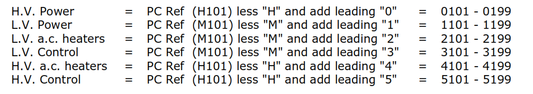
Therefore Cable number 1201 is constructed from:
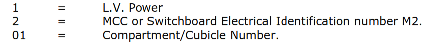
-
- When more than one cable of the same category is connected to any circuit, they shall be alphabetically suffixed, A through Z, so as to retain the philosophy of all cables associated with a particular circuit using the circuit reference number as a basis.
- Parallel power cables or multiple single core power cables shall be scheduled as one cable number and the “Cables in Run” entry in the cable schedule shall detail the number of cables to be installed.
- Parallel power cables shall be suffixed /1 and /2 and the multiple single cores suffixed with a “-” and a sequential number (e.g., /L1-1, /L2-1 and /L3-1for three single cores). See the following examples:
- 2 parallel cables = 1101/1 and 1101/2
- 3 x single cores = 1101/L1-1, 1101/L2-1 and 1101/L3-1
- 6 x single cores = 1101/L1-1, 1101/L2-1 and 1101/L3-1, and 1101/L1-2, 1101/L2-2 and 1101/L3-2
6.3 Non circuit Related Cables
- For Electrical Identification Numbers that do not apply (i.e., on the secondary side of general alarm panels), the cable numbers shall use zero as the second digit (i.e., the L.V. power cable numbers shall commence 1001, and the associated control cable numbers 3001).
- The terms of paragraph 6.2 shall still apply relative to “Power,” “Control,” and “a.c. heaters.”
Note: This procedure shall only be used if a common link cannot be found to enable all of the Conditions of paragraph 6.2 to be applied.
7. DISTRIBUTION BOARD NUMBERING
Distribution board numbers shall be formed using the prefix P730 and alphabetically suffixed reference letters. See the following examples:
-
- Lighting Distribution Board = P730A
- Trace Heating Distribution Board = P730B
8. LIGHTING AND SMALL POWER CABLE AND EQUIPMENT NUMBERING
8.1 Lighting and Small Power Cables
-
- For lighting and small power supplies that are taken from a distribution board, run in armored cable, and scheduled, the cable numbers shall be formed from the distribution board reference, the sub-circuit reference number, and the section of the circuit which is cabled (between fittings). See the following example:
- Distribution Board P730E, sub-circuit 12, section 2 = Cable number E/12/2
- For lighting and small power cables that are run in conduit or trunking, the circuit reference numbers shall not be shown on wiring or conduit routes, either on drawings or in the field.
- For lighting and small power supplies that are taken from a distribution board, run in armored cable, and scheduled, the cable numbers shall be formed from the distribution board reference, the sub-circuit reference number, and the section of the circuit which is cabled (between fittings). See the following example:
8.2 Lighting Fittings shall be numbered on the layout drawings, per circuit, using the circuit number as a prefix followed by /L and a sequential number. See the following example:
-
-
- Distribution Board P730E, circuit 11, sequential identification number L2 = Fitting number E/11/L2
-
8.3 Lighting Junction Boxes and Switches shall be numbered with the prefix LJB- or LS- and the Circuit number. See the following examples:
-
-
- Circuit = E10, Junction box = LJB-E/10
- Circuit = E12, switch = LS-E/12
-
8.4 Multiple Junction Boxes and Switches: If there is more than one junction box or switch, they shall be suffixed by a “/” and a sequential number. See the following examples:
-
-
- LS-E/12/1
- LJB-E/10/1
-
9. JUNCTION BOX NUMBERING (ELECTRICAL POWER, CONTROL, FIRE ALARM AND TRACE HEATING)
- In Power Circuits
- Junction boxes for power or control cables associated with a power circuit shall be formed by prefixing the power circuit reference with CJB- or PJB-. See the following examples:
- Junction box in power circuit M303, control function = CJB-M303
- Junction box in power circuit H101, control function = CJB-H101
- If more than one junction box is required in the same power circuit and for the same function, they shall be suffixed by a “/” and a sequential number. See the following examples:
- CJB-M303/1
- CJB-M303/2
- Junction boxes for power or control cables associated with a power circuit shall be formed by prefixing the power circuit reference with CJB- or PJB-. See the following examples:
- Other Junction Boxes
- Fire alarm system junction boxes shall be prefixed FJB-, followed by the zone number. See the following example:
- Fire alarm panel ref. FAP, Zone 01, = FJB-FAP/01
- Trace heating system junction boxes shall be prefixed HJB-, followed by the distribution board sub-circuit reference number. See the following example:
- Distribution Board ref. P730D, Sub-circuit /4, = HJB-D/4
- If more than one junction box is required in the same zone or circuit, they shall be suffixed by a “/” and a sequential number. See the following example:
- HJB-D/4/1
- For signals/controls from more than one circuit in a multi-core cable that are terminating at a common marshalling junction box, the box number shall be prefixed by “MJB-“. See the following example:
-
- MJB-ELEC
- If more than one junction box is required, they shall be suffixed by a “/” and a sequential number. See the following example:
- MJB-ELEC/1, /2, /3
-
- Fire alarm system junction boxes shall be prefixed FJB-, followed by the zone number. See the following example:
- Note: The Numbering Identification detailed in sections 7, 8, and 9 above shall be clearly and securely labeled in a prominent position on all of the relevant equipment, for all services.
10. FERRULE NUMBERING ON CONTROL CABLES
- Philosophy: Ferrules shall be used on cables for the following purposes:
- To establish a method by which it is possible to identify external sources of control voltage entering a switchboard or MCC terminals (other than via internal wiring).
- To enable interconnecting control signal cable cores to be traced between major equipment, panels, and MCCs. These could be run via junction boxes or intermediate devices.
- Method
- Note: See following figure for an illustration of the rules in this section.
- For a control voltage that is sent out from a switchboard or MCC, the ferrules shall indicate the PC reference number and the connected terminal number. See the following example:
- PC reference number = M303 terminating on terminal number 12; Ferrule = 12-M303
- For a control voltage that is brought in to a switchboard or MCC from remote equipment, the ferrules shall indicate the remote equipment reference number/tag and the connected terminals in that equipment. See the following examples:
- Remote control panel ref. number = 7, terminating on terminal number 89; Ferrule = 89-7
- Remote equipment ref. number = P108, terminating on terminal number 194; Ferrule = 194-P108
- For circuits with control cable cores wired via one or more intermediate devices other than “through junction boxes” (e.g., pushbuttons, and switches), before connecting back into a switchboard: there is no direct connection to the power circuit, so the core ferrule references shall be formed from the prefix C and a sequential number starting at 100, followed by the relevant power circuit reference number or the remote device/equipment number. See the following examples:
- Power Circuit reference number = M303, prefix for Ferrule number C100; Ferrule = C100-M303
- Remote Control Panel ref. number = 7, prefix for Ferrule number C101; Ferrule = C101-7
- Remote Equipment ref. number = P108, prefix for Ferrule number C102; Ferrule = C102-P108
- Where electrical control cables interface with instrument control cables, the instrument cable ferrule number shall be continued through onto the electrical control cable.
11. CONTROL STATION NUMBERING
- Control stations associated with power circuits shall be identified by a tag number previously allocated and shown on the P&IDs.
- All controlling devices/stations shall be shown on the P&IDs with their reference tag number.
