Following topics to be discussed here.
- Scope
- References
- Definition
- Design
- Fitting Design for ASME B16.11
- Pressure Rating
- Class Designation
- Inline Dimensions
- Socket welding Ends
- Threaded Ends
- Integrally Reinforced Outlet Fittings
- Specific Fittings Type
- Elbows
- Tees
- Couplings
- Reducing Fittings
- Integrally Reinforced Outlet Fittings
- Material Applications for Specific Services
- Purchase Description
- Marking
FIGURE 1 – Fitting Consolidation Gap Allowance
- TABLE I – Co-relation of Fitting Class with Pipe Wall Designation
- TABLE II – Services and Materials

Forged Fittings Selection for Industry
1. Scope
1.1 This article is for selection of forged socket weld and threaded fittings for piping, and pipelines. Selection includes material, pressure rating, dimensions, and marking.
The type of fittings includes, but is not limited to elbows, 45° elbows, tees, caps, and couplings in threaded and socketweld ends. The size range is NPS 1/2 to NPS 1 1/2 for socket weld and threaded, to NPS 4 for classes that are threaded only, and all appropriate size combinations for integrally reinforced outlet fittings.
1.2 This article supplements the requirements of ASME B16.11, B16.28 & MSS SP-75 standards for forged fittings, and ASME B31.1, B31.3, B31.4 & B31.8 piping codes.
1.3 Cast fittings are excluded from the scope of this standard. Custom designed fittings may be specified to the provisions of this standard, but shall include a drawing with engineering details included, or with a supplemental duty specification.
2. References
Reference is made in this article to the following documents.
American Petroleum Institute (API)
- 941 Steel for Hydrogen service at elevated temperatures and pressures in petroleum refineries and petrochemical plants .
American Society for Testing and Materials (ASTM)
- A 105 Carbon steel forgings for Piping applications.
- A 182 Forged or Rolled Alloy Steel Pipe flanges, forged fittings and valves and parts for High Temperatures services
- A 350 Carbon and Low Alloy Steel forgings, Requiring notch toughness testing for piping components
- A 694 Carbon and alloy steel forgings for pipe flanges, fittings, valves, and parts for High pressure transmission service
- A 707 Forged carbon and alloy steel flanges for Low Temperature Service
- B 462 Specification for forged or rolled UNS NO.8020, UNS NO 8024, UNS NO 8026, UNS NO 8367 and UNS R20033 Alloy pipe flanges, forged fittings and valves and parts for corrosive High temperature service.
- B 564 Specification for Nickel Alloy Forgings
American Society of Mechanical Engineers (ASME)
- B16.9 Factory-made Wrought Butt Welding Fittings
- B16.11 Forged Fittings, Socket-Welding and Threaded
- B16.25 Buttwelding Ends
- B16.28 Wrought Steel Buttwelding Short Radius Elbows and Returns
- B31.1 Power Piping
- B31.3 Process Piping
- B31.4 Pipe Line Transportation system for liquid hydro carbons and other liquids
- B31.8 Gas Transmission and Distribution Piping Systems B36.10M Welded and Seamless Wrought Steel Pipe Section III Boiler and Pressure Vessel Code
Manufacturers Standardization Society (MSS)
- SP-75 Specification for high-test Wrought,Butt Welding Fittings
- SP-97 Integrally reinforced Forged Branch Outlet Fittings – Socket welding, Threaded and Butt welding Ends
National Association of Corrosion Engineers (NACE)
MR0175/ISO15156 Petroleum and natural gas Industries-Materials for use in H2S Containing environments in oil and production-Part 1, Part 2 & Part 3
3. Definitions
For the purpose of understanding this standard, the following definitions apply.
Basic Material. The generic material. Carbon steel, low alloy 1 1/4 Cr 1/2 Mo, and type 304/316 stainless steel, are examples of basic materials.
High Strength Material. Includes fittings for API 5L pipe-Grade X42 to X65.
JIS. Japanese Industrial Standards.
Manufacturing Standard. The manufacturing standard is the National Standard that describes the process of manufacturing from basic material to finishing and testing. Examples of manufacturing standards are ASTM, and API.
National Standard. National standard is a material or design standard generated by a nation or group. The primary National Standards accepted by SABIC are those of the United States, and generally are defined by ASME, ASTM, API, or MSS.
Purchase Description. The information to purchase, inspect, and warehouse the item.
Severe Cyclic Conditions. Conditions in which the computed displacement stress range exceeds 0.8 times the allowable stress range, and the equivalent number of cycles is greater than 7000 or other conditions which the designer determines will produce an equivalent effect.
4. Design
4.1 Fitting Design for ASME B16.11
4.1.1 The National Standard for socket weld and threaded fittings shall be ASME B16.11. Other National Standards that will produce fittings that will fit into the dimensional envelope, provide the same or higher ratings, and satisfy the end conditions of ASME B16.11, shall be acceptable.
4.1.2 Socket weld fittings manufactured to JIS standards that do not meet the criteria for end conditions as per B16.11 shall not be acceptable.
4.1.3 When socket weld or threaded fittings are required, but no forging material standard is available for the material, the fittings shall be specified with the wrought material standard for the material, in accordance with ASME B16.11, paragraphs 1.1.2 and 5.1.
4.2 Pressure Rating
The allowable pressure rating shall be determined by calculation as for straight seamless pipe of equivalent material. The wall thickness used in the computation shall be that tabulated in ASME B36.10M for the size and applicable schedule of pipe, reduced by appropriate manufacturing tolerances and allowances.
4.3 Class Designation
The usage of ASME B16.11 fittings shall be in accordance with the governing ASME B31 code. ASME B16.11 fittings are designated by pressure ratings. Table I tabulates the relationship between the various pressure ratings as assigned by ASME B16.11 for use with a specific schedule number or wall designation of pipe.. No further calculations are necessary to select a fitting.
4.4 Inline Dimensions
Inline dimensions shall be in accordance with the tables in ASME B16.11. These dimensions are necessary to ensure correct fit in the piping design.
4.5 Socket welding Ends
Socket welding ends shall be in accordance with ASME B16.11. Forged fittings with socket weld ends shall be limited to NPS 1 1/2 maximum.
4.6 Threaded Ends
Threaded ends shall be in accordance with ASME B16.11. Forged fittings with threaded ends shall generally be limited to NPS 1 1/2 , but shall be extended to NPS 4 in classes where threading is the only acceptable means of joining, for example galvanized piping.
4.7 Integrally Reinforced Outlet Fittings
4.7.1 Integrally reinforced outlet fittings offer an alternative means of connecting into the header pipe, and do not require reinforcement. Integrally reinforced outlet fittings are proprietary, but the design shall conform to MSS SP-97, to avoid size, weight, and dimensional variations from one manufacturer to another.
4.7.2 Because of ASME B31 (31.1, 31.3,) & B 16.9 acceptance of MSS SP-97, all of the designs generated in accordance with MSS SP-97 also conform to these standards.
4.7.3 ASME B31.1, 31.3, and ASME Section III require a branch connection to restore the full strength of the run pipe weakened by the hole cut for installation.
Strength replacement may be accomplished by adding excess material in the branch connection. It shall be ensured that the integrally reinforced outlet fittings and the deposited weld metal used to attach the fittings to run pipes contain all the reinforcement required by the applicable codes, without the addition of saddles or pads. Manufacturers shall prove their product design with either proof tests or specific reinforcement calculations.
4.7.4 The size convention for integrally reinforced outlet fittings shall be with the outlet size as the first size, the header size following. For example, an NPS 4 branch on an NPS 10 header shall be called out as 4 x 10. Socketweld and threaded outlets shall be specified by pressure ratings. Buttweld outlets shall be specified by pipe wall or schedule. Thus, fittings that have a butt weld outlet will have two sizes and two walls. For example, an NPS 4 schedule 40 branch on an NPS 16 schedule 40 header shall be called out as NPS 4 sch 40 x NPS 16 sch 40.
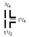
4.7.5 Manufacturers group header sizes together for economic reasons. It shall be ensured that the designated consolidation gap does not exceed the 1.6 mm (1/16 in) ‘gap’ tolerance of the fitting, see Figure 1.
4.7.6 Integrally reinforced outlet fittings shall meet the applicable provisions of MSS SP-97.
4.7.7 Threaded and socketweld outlets on integrally reinforced outlet fittings shall be limited to NPS 1 1/2 .
4.7.8 Ends for integrally reinforced outlet fittings shall be as follows:
-
- Buttweld outlets shall be in accordance with ASME B16.25
- Socketweld and threaded ends shall be in accordance with ASME B16.11
5. Specific Fittings Types
5.1 Elbows
The wall thickness at the crotch area of elbows shall be the sum of the pipe wall thickness and the socket thickness. In cases where there is a high corrosion or erosion rate at elbows, one or more classes higher than the pipe wall may be selected, to offset the higher rate of material loss in the more turbulent areas.
5.2 Tees
The wall thickness at the crotch area of the outlet shall be the sum of the pipe wall thickness and the socket thickness. The size of the run opening shall be specified first, followed by the size of the branch.
5.3 Couplings
Couplings used for inline service shall be full couplings.
5.4 Reducing Fittings
Reducing fittings have two sizes. ASME B16.11 defines the size convention. The size of the largest run opening shall be specified first, followed by the size of the opposite end of the run. The size of the branch shall be given last e.g. 11/2 x 3/4 x 11/4.
Reducing fitting sizes shall be limited to those listed in ASME B16.11. Reductions should be made with swage nipples whenever possible. Threaded bushing shall not be allowed
5.5 Integrally Reinforced Outlet Fittings
5.5.1 The preferred method for branch connection shall be by use of a tee, or a reducing tee. When the header to branch size combination is not available, a reinforced stub-in shall be acceptable in Category ‘D’ fluid service, and an integrally reinforced outlet fitting shall be required for all other services. A half coupling is suitable for threaded and socketweld branches in water services, as a reinforced stub-in. Final selection shall be in accordance with the tables in SABIC standard.
5.5.2 Set-in fittings (sweepolet, or vesselet) shall be selected for severe cyclic services, in accordance with ASME B31.3, in size combinations outside of the range of reducing tees listed in ASME B16.9, or where size restrictions will not allow a reducing tee.
5.5.3 Set-on fittings (weldolets, threadolets, sockolets, elbolets, and laterolets) shall be selected to provide branch reinforcement, when required, for branches in buttweld sizes, in combinations outside of the range of reducing tees in ASME B16.9.
5.5.4 Set-on fittings for 90 branches shall be selected for branch connections for piping in sizes that use socketweld, or threaded construction, or threaded taps.
5.5.5 Set-on fittings that are specifically designed to produce a tap on a buttweld fitting, for example Thermowell, shall be selected with a buttweld, socketweld, or thread, as applicable.
5.5.6 Set-on fittings that are specifically designed to produce lateral connections on pipe shall be selected to make lateral connections, rather than using lateral fittings. Set-on fittings shall also be selected to produce lateral branches in socketweld and threaded piping.
6. Material Applications for Specific Services
6.1 Materials shall conform to the PIP specifications listed in SES P02-S01, P02-S14, P03-S01 & P04-S01. Fittings shall have a purchase description as per SES P31- G01.
6.2 When an in-plant service has water and H2S in concentrations that conform to the levels specified in NACE MR0175/ISO15156 , that service shall be considered NACE service. The purchase order for fittings in those services shall contain the word ‘NACE’.
6.3 High strength materials for pipeline service are fittings conforming to API 5L, pipe Grades X42 to X65. When forged fittings and integrally reinforced outlet fittings are used in pipeline service, with high strength material, the ASTM grade selected shall include the ‘F’ grades, so the specified minimum yield strength (SMYS) will be equal to the strength of the pipe.
6.4 Galvanized fittings shall be coated with zinc by hot dip process conforming to ASTM A 153.
6.5 Table II lists materials for typical services, based on general relationships between service, temperature, and size. These are derived from the relevant PIP/SESs, but also include additional materials and service requirements for generation of future material classes. Final material selection shall be made by a qualified metallurgist. The table is divided into carbon steel, low and intermediate alloy, stainless steel, and selected common high alloys. The table is for forged pipe fittings in accordance with ASME B16.11 & in accordance with MSS SP 97 for integrally reinforced outlet fittings.
7. Purchase Description
The following information shall be included in the purchase description:
- Type of fitting b. Rating
- c. Dimensional standard d. End connection
- Material
- f. Material grade
- Additional material and testing requirements, if applicable h. Nominal size of fitting
- i. Wall thickness as defined by schedule, weight or actual decimal wall j. Additional requirements
8 Marking
8.1 Fittings shall be marked in accordance with ASME B16.11, paragraph 4. Fittings shall be protected against mechanical damage during shipping. Each fitting shall be permanently marked to show the following:
-
- Manufacturer’s name or trade mark
- Material and product identification (ASTM or ASME grade symbol), with conformance to these standards indicated by the prefix ‘WP’ in the grade symbol
- c. Class designation (3000, 6000, 9000), Schedule number, or nominal wall thickness designation NPS
8.2 Visually, fittings shall have a smooth surface and shall be free of burrs and sharp edges. Mating surfaces shall fit-up without gaps.
FIGURE 1 – Fitting Consolidation Gap Allowance

TABLE I – Co-relation of Fitting Class with Schedule Number or Pipe Wall Designation

TABLE II – Services and Materials
