Following topics to be discussed here.
1. SCOPE
2. REFERENCES
3. GENERAL
4. SAFETY
5. MATERIALS
5.1 Welding Electrodes
5.2 Shielding Gas
5.3 Electrical Equipment and Operation
6. WORKMANSHIP
6.1 Preparation of Materials for Welding
6.2 Joint Designs
6.3 Weld Backup
6.4 Welding Techniques
7 INSPECTION
TABLE
I Welding Current Versus Nozzle Size
II Shielding Gas Flow Rates
FIGURES
- Schematic Description of Pulsed Current
- Square-Edge Butt Joints
- Single-V Butt Joints
- Single-U and Double-U Joints
- Double-V Butt Joint
- Lap Joint
- Corner Joints
- Tee Joints
- Edge Joint
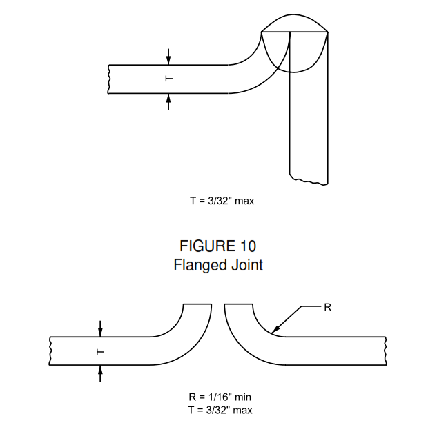
- Flanged Joint
1. Scope
1.1 This standard provides general practices for gas tungsten arc welding (GTAW).
1.2 Non destructive testing is beyond the scope of this standard.
2. References
Reference is made in this standard to the following documents.
American Society of Mechanical Engineers (ASME)
B31.1 Power Pipe
B31.3 Process Pipe
3. General
3.1 GTAW is a fusion-welding process employing an arc between a nonconsumable electrode and the work, with provision for supplying a protective shield of inert gas around the electrode, over the weld and the adjacent base metal surface. The process may or may not require the addition of filter metal.
3.2 This process utilizes a specially constructed electrode holder which incorporates a relatively nonconsumable tungsten, or tungsten alloy electrode, and a concentric metal or ceramic nozzle to direct the flow of shielding gas.
4. Safety
4.1 Safe practices prescribed in SES W02-F01 shall be followed on plant sites.
4.2 Welding torches which have a maximum current rating in excess of 150 A shall be water-cooled in order to make the equipment lightweight and flexible for easy handling.
4.3 The cooling water shall be clean in order to avoid plugging of passages, causing overheating and damage to the equipment. Therefore, it is advisable to place a water strainer or filter in the water line ahead of the torch.
4.4 If the water supply pressure exceeds 3.8 kg/cm2, a pressure regulator shall be placed in the supply line to prevent possible damage to the water hose.
4.5 The water hose shall be tested to 1 1/2 times the maximum water pressure available at the connection.
4.6 Welding torches having a maximum current capacity of 300 A require a minimum cooling water flow rate of 45 to 50 L/h.
4.7 Provision shall be made for an open cooling water drain line from the torch in order to avoid any possibility of the drain line being closed while the torch is in operation. A closed drain line may lead to the formation of steam in the cooling water passages of the torch which could rupture and cause injury to the operator.
4.8 When a supply of cooling water is not readily available, a completely self-contained recirculating cooling-water unit shall be used, consisting of a pump and a tank large enough to prevent the water temperature from exceeding 60 °C (140 °F).
5. Materials
5.1 Welding Electrodes
5.1.1 “Clean-finish” rather than “centerless-ground” – pure tungsten, thoriated-tungsten, or zirconium-tungsten electrodes are recommended. Thoriated-tungsten and zirconium-tungsten electrodes have a higher current capacity and give a more stable arc than pure tungsten electrodes when welding with high-frequency stabilized Alternating Current (ac). Also, in Direct Current (dc) straight-polarity welding, electrode surface temperatures are lower, therefore, electrode consumption is less rapid with thoriated-tungsten and zirconium-tungsten electrodes than with pure tungsten electrodes. When welding aluminum heavier than 12 mm (1/2 in) thick, pure tungsten is recommended because the weld pool is controlled more easily with the softer arc provided by the pure tungsten.
5.1.2 Electrode sizes for various ranges of operating current are given in Table I.
5.1.3 When using dc, straight polarity, it is necessary, before use, to grind the electrode on a taper or a sharp point. The operating current then will cause the end of the electrode to seek its own best diameter, thus providing maximum electrode current density and minimizing arc wandering.
5.1.4 The electrode shall extend 6-9 mm ( 1/4-3/8 in) maximum beyond the end of the gas cup for butt welding, and about 6-9 mm (1/4-3/8 in) for fillet welding. The electrode shall not extend more than 2 mm (3/32 in) beyond the end of the cup when welding aluminum pipe or plate with high-frequency ac. For applications requiring electrode extension in excess of that specified here, see 5.2.5.1.
5.2 Shielding Gas
5.2.1 Welding grade argon (minimum purity of 99.99 percent) or helium (minimum purity of 99.9 percent) or mixtures of these gases shall be used as the shielding gas. Argon is most widely used. Helium is used for welding aluminum, and manganese with straight polarity. For a given value of welding current, the heat input is higher with helium than with argon, owing to the higher voltage of the helium arc.
5.2.2 Gases are supplied in high-pressure steel cylinders, or, for large-scale usage, in bulk storage tanks. A regulator is required to reduce the cylinder pressure to a working pressure of approximately 138 kPa. In addition, a flowmeter is required, since different welding conditions require different rates of gas flow for proper protection. Combination regulator-flowmeters are available which combine the functions of the regulator and the flowmeter in one unit.
5.2.3 Tubing and connections for the inert-gas supply shall be clean and dry. The torch shall be clean and in good mechanical condition. Any water and gas leaks shall be repaired immediately. Avoid pinching the gas supply tubing and stopping the gas flow.
5.2.4 Drafts shall be avoided during welding; in some cases, as in field welding, it may necessary to shield the welding area from wind gusts to prevent loss of gas coverage.
5.2.5 Torch nozzle sizes shall be selected to provide adequate gas coverage of the weld area. In general, the nozzle size shall be increased as the welding current is increased, see Table I. Since higher currents require larger diameter electrodes and produce larger sizes of weld pool, a larger area of protective gas blanket is required. Defective cups or nozzles shall be replaced promptly.
5.2.5.1 For applications requiring improved gas coverage, for example, welding reactive materials or weldments, which require a tungsten stick-out in excess of that specified in 4.1.4, the so-called torch gas lens shall be employed. This devise is a collet body with a series of wire screens which provide a nonturbulent, collimated gas flow and allow for a higher shielding gas flow rate, and, hence, will not aspirate air into the weld area.
5.2.6 Recommended shielding gas flow rates for various ranges of welding current are given in Table II. Poor weld quality may result from using excessively high rates of gas flow as well as from using insufficient rates of flow. An excessive rate of shielding gas flow may produce turbulence in the gas steam, causing admixture of the inert gas with the surrounding atmosphere, thus reducing the effectiveness of the protective gas shield.
5.2.7 Mechanical or electrical devices for shutting off gas flow when not welding are recommended for conserving gas.
5.3 Electrical Equipment and Operation
5.3.1 Power for gas tungsten arc welding is obtained from either a standard welding generator or rectifier for dc welding, or from a special welding transformer for ac welding.
5.3.2 Combination transformer-rectifier welders are available as single machine units which permit selection of either dc or ac, with or without high frequency, for both inert-gas and coated-electrode arc welding.
5.3.3 The ac transformers for GTAW are available in two basic types. One type employs a high open-circuit secondary voltage to provide arc stability, intermittent high-frequency stabilization for arc starting, and series capacitors to provide a balance wave-form for aluminum welding. The other type employs a lower open-circuit secondary voltage and continuous high-frequency stabilization to provide arc stability. The latter type does not usually contain series capacitors, and it is necessary for the manufacturer to rate the output current conservatively, because of saturation and heating effects of the unbalanced current wave-form. Experience indicates that there is no significant difference in the quality of welds produced by one type of transformer or the other.
5.3.4 When buying a welding power supply for versatile use in the shop and field, one shall be selected which will provide a sufficiently low stable output current to permit satisfactory welding of thin-gage materials. Machines having a minimum output current of 10-15 A, and a maximum current of 300 A at 60 percent duty cycle usually are adequate for manual welding a variety of materials over a wide thickness range.
5.3.5 A dc of straight polarity using argon is preferred for welding most materials. Where aluminum alloys, magnesium alloys, and aluminum bronze are welded, helium gas is substituted for argon. However, the use of high-frequency stabilized ac is frequently desirable for manual welding thin-gage materials of all types because of the lower heat input which ac provides by the high-frequency stabilization. The use of ac is preferred for manual welding aluminum alloys, magnesium alloys, and aluminum bronze.
5.3.6 A pulsed current mode can be used also for GTAW. A pulsed current power supply is a conventional drooping volt-ampere characteristic power source which has the capability of pulsing between a low level current referred to as a background current and a high level referred to as a peak current. Pulsed current power sources used for gas tungsten arc welding have pulse frequencies that vary from 0 to 20 Hz, and pulse width that are variable. The pulse ratio is usually a function of time. See Figure 1 for schematic explanation and terminology. Power sources can be purchased which already have pulse current capabilities built into them. For conventional steady current power sources, add-on packages are also available which will provide pulsed current within a range of pulse frequencies. The same features of up slope of weld current, decay or taper of weld current, and down slope of weld current can be obtained on pulse current power sources, with the same or similar to steady current power sources.
5.3.6.1 Arc Pulsing Units – Welding current pulse control is effected by circuits which pulse the power supply output. The pulse unit switches the arc between two current levels with independently adjustable time durations for the peak and background currents. Pulsing the current permits more precise control over weld bead shape, penetration, and heat input. It provides control that other systems do not. In addition, it can be generally stated that less welder skill is required for pulsed gas tungsten arc welding than for steady-state current gas tungsten arc welding.
6. Workmanship
6.1 Preparation of Materials for Welding
6.1.1 Cutting – Depending upon the materials involved, there are a variety of methods available for preparing joints for welding. Mechanical methods of joint preparation (for example: machining, sawing, abrasive cutting, grinding, sanding, or filing) are used widely. On some materials, thermal cutting methods, (for example: oxyacetylene flame, air, carbon arc, plasma arc, GTAW, or coated-electrode arc cutting) are used. The surfaces of the cut, bevel, and adjacent metal shall be cleaned to bright metal.
6.1.2 Cleaning – All surfaces in and adjacent to the joint to be welded and filler wire shall be clean before welding. Oil, grease, dirt, crayon marks, paint, and rust shall be removed from the surfaces.
6.1.3 Assembly
6.1.3.1 In order to obtain good weld quality, joints must be accurately fitted and aligned. Fit-up tolerances are shown for various joint designs on Figures 2 to 10. Unless otherwise indicated, the maximum joint gap shall not exceed one-half the thickness of material being welded, or 3 mm ( 1/8 in), whichever is smaller.
6.1.3.2 Misalignment of joints for butt welding shall be held within the following tolerances: for thicknesses up to 12 mm (1/2 in), 1.5 mm (1/16 in) misalignment maximum; for sheet-metal work, if possible, the work shall be clamped firmly in a jig fitted with a copper backup strip. Welds made under the jurisdiction of recognized Codes shall meet alignment tolerances of the applicable Code. Otherwise, the pieces to be joined shall be supported to provide plate alignment within 25 percent of the material thickness or 3 mm (1/8 in), whichever is less. For pipe alignment, see ASME B31.1 or B31.3.
6.1.4 Tack Welding – Tack welding shall be done only by qualified welders. The same care shall be employed in tack welding as in depositing the first weld bead. The following is recommended average practice for number and size of tack welds. In some cases, experience may dictate the need for additional tack welds in order to maintain the proper joint fir-up and alignment.
6.2 Joint Designs
6.2.1 Butt Joints
6.2.1.1 The square-edge butt joint is used in manually welding materials up to 9 mm (3/8-in) thick. Where the joint is provided with a solid backup, or where the joint can be partially welded from one side and finished from the other side. For joints to be welded from one side only, and which are not solidly backed, the square-edge butt joint shall not be used for thicknesses exceeding 3 mm (1/8 in). Joint fit-up shall be true enough to provide complete and uniform penetration of fusion. Misalignment of surfaces shall not exceed 20 percent of the thickness. For unbacked joints, the maximum joint gap shall not exceed one-half of the thickness or 3 mm (1/8 in), whichever is less. Sketches of square-edge butt joints are shown on Figure 2.
6.2.1.2 The single-V butt joint is used for material thicknesses ranging from 3-25 mm (1/8-1 in). Sketches of single-V joints are shown in Figure 3. The maximum misalignment shall not exceed 20 percent of the thickness, for thicknesses up to 12 mm (1/2 in), and 3 mm (1/8in) for thicknesses over 12 mm (1/2 in).
6.2.1.3 Double-V, double-U, and single-U joints are used for material thicker than 12 mm (1/2 in), where the design permits access for welding from both sides of the joint. After welding from one side, it may be necessary to grind the joint from the back side until sound metal is reached, before welding on the back side. Sketches are shown on Figures 4 and 5.
6.2.2 Lap Joints – In order to make a good lap weld, the plates shall be in close contact along the entire length of the joint. Tack welding at frequent intervals may be required. On material 6 mm ( 1/4-in) thick or less, lap joints can be made with or without filler rod. When no filler metal is used, care shall be taken to avoid low spots or burn-through. See Figure 6 for a lap joint.
6.2.3 Corner Joints – Joint details for corner joints are shown in Figure 7. With good fit-up, corner joints in material less than 3 mm (1/8-in) thick generally can be made without addition of filler metal. Thicker joints usually require adding filler metal in order to provide adequate reinforcement.
6.2.4 Tee Joints – Joint details for tee joints are shown on Figure 8. When complete penetration or fusion is required (as shown on Figures 8B and 8C), care shall be taken that the welding current values are adequate for the thickness of the web material.
6.2.5 Edge Joints and Flanged Joints – Edge joints and flanged joints as shown on Figures 9 and 10, are used solely on light-gage material and usually require no filler rod addition. Preparation is simple, and the joint economical to weld. The edge joint shall not be used, however, where direct tension or bending stresses will be applied to the finished joint. It may fail at the root under relatively low stress loads.
6.3 Weld Backup
6.3.1 Metal Backup Bars
6.3.1.1 Removable flat metal backup bars shall be used only on joints like the flange type shown on Figure 10, where the bar does not actually touch the weld zone. If the bar comes in contact with the under- side of the weld, nonuniform penetration is obtained and the weld underside will be rough and uneven.
6.3.1.2 A removable, grooved backup bar is commonly used. The groove shall be approximately 0.1-0.3 mm (0.007-0.012-in) deep and approximately ten times as wide as the thickness of material being welded but not less than 4 mm (3/16 in).
6.3.1.3 A copper bar may be used to back welds in stainless steel or high-nickel alloys; on aluminum or magnesium, the bar shall be made of steel or stainless steel. Backing bars for welding thick materials are often water-cooled to prevent excessive heat build-up in the weld zone.
6.3.2 Consumable Metal Inserts – Consumable metal inserts having special cross sections are available commercially for pipe welding. Joint surfaces shall be machined to close tolerances for proper fit-up of these inserts. A gas backup is necessary during welding.
6.3.3 Gas Backup – Gas backup techniques for welding are described in detail in SES W13-F01.
6.4 Welding Techniques
6.4.1 Arc Starting
6.4.1.1 In high-frequency ac welding, the electrode does not have to touch the workpiece to start the arc. The superimposed high-frequency current jumps the gap between the welding electrode and the work, thus establishing a path for the welding current to follow. To strike an arc, first the welding current and shielding gas is turned on, and gradually the torch is brought toward the work. When the electrode is within about 3 mm (1/8 in) from the work surface, the arc will strike.
6.4.1.2 In dc welding, the same motion is issued for striking an arc. However, in this case, the electrode touches the workpiece in order for the arc to start. As soon as the arc is struck, the electrode is withdrawn to provide an arc gap of 1-3 mm (0.040-1/8 in), depending upon the material being welded.
6.4.1.3 The arc shall be struck on the bevel, on the work area itself or on a heavy piece of copper or scrap steel, and then carried to the starting point of the weld. A carbon block shall not be used for starting the arc, as the electrode becomes contaminated which causes the arc to wander.
6.4.2 Stopping the Arc
6.4.2.1 Care shall be taken in stopping the arc to avoid forming crater cracks and porosity. One of the most effective methods is to decrease the size of the weld pool gradually by decreasing the current with a
foot-controlled rheostat. When filler metal is being used, adding a small quantity of metal from the rod just as the electrode is being withdrawn will compensate for the solidification shrinkage of the weld pool and help to prevent a large shrinkage cavity forming. Moving the arc rapidly over the side of the bevel is effective in minimizing disturbance of the final weld pool. A gradual breaking of the arc will reduce the possibility of porosity and crater cracking. “Fish-tail” crater cracks shall be removed from all tack welds before subsequent weld passes are deposited.
6.4.2.2 After the arc has been stopped, it is good practice to play the shielding gas from the torch over the end of the weld to permit this area to cool under the protective gas. At the same time, this allows the tungsten to cool under the gas and prevents its oxidation.
6.4.3 Electrode Contamination – Weld carefully to avoid inclusion of tungsten in the weld. If the electrode tip is melted or contaminated by contact with the filler wire or weld pool, welding shall be stopped and the end of the electrode shall be ground. The weld shall be cleaned before welding is started again, by chipping or grinding where necessary to remove contaminated metal.
6.4.4 Butt Welding
6.4.4.1 After the arc has been struck, the torch is held at an angle pointed in the direction of travel. The starting point of the work is first preheated by moving the torch in small circles until a molten puddle is formed. An arc length of 1-3 mm (0.040-1/8 in), depending upon the material being welded, shall be maintained. When the puddle becomes bright and fluid, the torch is moved slowly and steadily along the joint at a speed that will produce a bead of uniform width.
6.4.4.2 When the addition of filler metal is necessary, a forehand technique is used; the filler rod is held about 15 degrees to the work and about 25 mm (1 in) away from the starting point. First the starting point is preheated and the puddle is developed as described above. When the puddle becomes fluid, filler metal is added. When withdrawing the rod, the hot end shall be kept under the gas blanket. The oxidized end of the filler rod shall be trimmed approximately 12 mm (1/2 in) before each subsequent welding pass, or at each time it is withdrawn from the weld pool. The rate of forward speed and amount of filler metal added will depend upon the desired width and height of the bead.
6.4.4.3 Multipass welding will generally be necessary for welding material over 6 mm (1/4-in) thick in the flat position, and perhaps for thinner materials in the horizontal and overhead position. The number of passes required will depend upon the thickness of material, the current-carrying capacity of the equipment involved, and the geometry of the assembly being fabricated. The first pass, or “root” pass, shall provide complete penetration of fusion at the bottom of the joint. Subsequent passes can be made at higher currents, owing to the backup effect of the root weld. Care shall be taken to prevent cold overlaps between beads and layers. When bead surfaces become oxidized, they shall be wire brushed to prevent oxide inclusions in subsequent passes. On heavy work, it is sometimes advantageous to carry all the beads along simultaneously in a staggered arrangement to utilize the residual heat of preceding passes. Selection of the procedure to be used depends upon experience.
6.4.4.4 For making vertical butt joints, the weld is usually made from bottom to top. When filler metal is necessary, it is added from the top or leading edge of the puddle, in the same manner as described in 6.4.4.2.
6.4.5 Lap Welding
6.4.5.1 A lap weld or joint is started by first developing a puddle on the bottom sheet. When the puddle becomes bright and fluid, the arc is shortened to about 1.6 mm (1/16 in). The torch is oscillated directly over the joint until the sheets are firmly joined. Once the weld is started, the oscillating movement is no longer
6.4.1.3 The arc shall be struck on the bevel, on the work area itself or on a heavy piece of copper or scrap steel, and then carried to the starting point of the weld. A carbon block shall not be used for starting the arc, as the electrode becomes contaminated which causes the arc to wander.
6.4.2 Stopping the Arc
6.4.2.1 Care shall be taken in stopping the arc to avoid forming crater cracks and porosity. One of the most effective methods is to decrease the size of the weld pool gradually by decreasing the current with a foot-controlled rheostat. When filler metal is being used, adding a small quantity of metal from the rod just as the electrode is being withdrawn will compensate for the solidification shrinkage of the weld pool and help to prevent a large shrinkage cavity forming. Moving the arc rapidly over the side of the bevel is effective in minimizing disturbance of the final weld pool. A gradual breaking of the arc will reduce the possibility of porosity and crater cracking. “Fish-tail” crater cracks shall be removed from all tack welds before subsequent weld passes are deposited.
6.4.2.2 After the arc has been stopped, it is good practice to play the shielding gas from the torch over the end of the weld to permit this area to cool under the protective gas. At the same time, this allows the tungsten to cool under the gas and prevents its oxidation.
6.4.3 Electrode Contamination – Weld carefully to avoid inclusion of tungsten in the weld. If the electrode tip is melted or contaminated by contact with the filler wire or weld pool, welding shall be stopped and the end of the electrode shall be ground. The weld shall be cleaned before welding is started again, by chipping or grinding where necessary to remove contaminated metal.
6.4.4 Butt Welding
6.4.4.1 After the arc has been struck, the torch is held at an angle pointed in the direction of travel. The starting point of the work is first preheated by moving the torch in small circles until a molten puddle is formed. An arc length of 1-3 mm (0.040-1/8 in), depending upon the material being welded, shall be maintained. When the puddle becomes bright and fluid, the torch is moved slowly and steadily along the joint at a speed that will produce a bead of uniform width.
6.4.4.2 When the addition of filler metal is necessary, a forehand technique is used; the filler rod is held about 15 degrees to the work and about 25 mm (1 in) away from the starting point. First the starting point is preheated and the puddle is developed as described above. When the puddle becomes fluid, filler metal is added. When withdrawing the rod, the hot end shall be kept under the gas blanket. The oxidized end of the filler rod shall be trimmed approximately 12 mm (1/2 in) before each subsequent welding pass, or at each time it is withdrawn from the weld pool. The rate of forward speed and amount of filler metal added will depend upon the desired width and height of the bead.
6.4.4.3 Multipass welding will generally be necessary for welding material over 6 mm (1/4-in) thick in the flat position, and perhaps for thinner materials in the horizontal and overhead position. The number of passes required will depend upon the thickness of material, the current-carrying capacity of the equipment involved, and the geometry of the assembly being fabricated. The first pass, or “root” pass, shall provide complete penetration of fusion at the bottom of the joint. Subsequent passes can be made at higher currents, owing to the backup effect of the root weld. Care shall be taken to prevent cold overlaps between beads and layers. When bead surfaces become oxidized, they shall be wire brushed to prevent oxide inclusions in subsequent passes. On heavy work, it is sometimes advantageous to carry all the beads along simultaneously in a staggered arrangement to utilize the residual heat of preceding passes. Selection of the procedure to be used depends upon experience.
6.4.4.4 For making vertical butt joints, the weld is usually made from bottom to top. When filler metal is necessary, it is added from the top or leading edge of the puddle, in the same manner as described in 6.4.4.2.
6.4.5 Lap Welding
6.4.5.1 A lap weld or joint is started by first developing a puddle on the bottom sheet. When the puddle becomes bright and fluid, the arc is shortened to about 1.6 mm (1/16 in). The torch is oscillated directly over the joint until the sheets are firmly joined. Once the weld is started, the oscillating movement is no longer necessary. The torch is moved along the seam, holding the end of the electrode just above the edge of the top sheet.
6.4.5.2 In lap welding, the puddle developed will be boomerang or V-shaped. The center of the puddle is called the “notch,” and the speed at which this notch travels will determine how fast the torch can be moved ahead. Care shall be taken that this notch is completely filled in for the entire length of the seam. Otherwise, it is impossible to achieve complete fusion at the sides of the joint and good penetration at the root.
6.4.5.3 When filler metal is used, faster welding speeds are possible as the rod helps fill up the notch. Care must be taken to get complete fusion, however, and not merely to lay in bits of filler rod on cold, unfused base metal. By carefully controlling the melting rate of the top edge, and by adding just the right amount of the filler metal where needed, a good uniform bead of proper proportions can be obtained.
6.4.6 Edge or Corner Welding – A puddle is developed at the stating point, then the torch is moved straight along the joint. Travel speed is regulated to produce a uniform-looking bead. Too slow a welding speed will cause molten metal to roll off the edge. Irregular, or too high speeds will produce a rough, uneven surface. Usually, no filler metal is required.
7. Inspection
The amount and type of inspection required depends upon the service conditions and hazards to personnel and property. It is the responsibility of the originator to define the inspection requirements. Inspection shall be in accordance with applicable code(s).
TABLE I – Welding Current Versus Nozzle Size
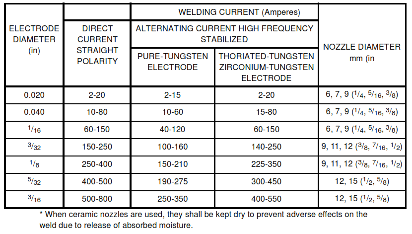
TABLE II – Shielding Gas Flow Rates
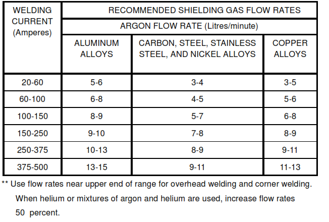
FIGURE 1 – Schematic Description of Pulsed Current
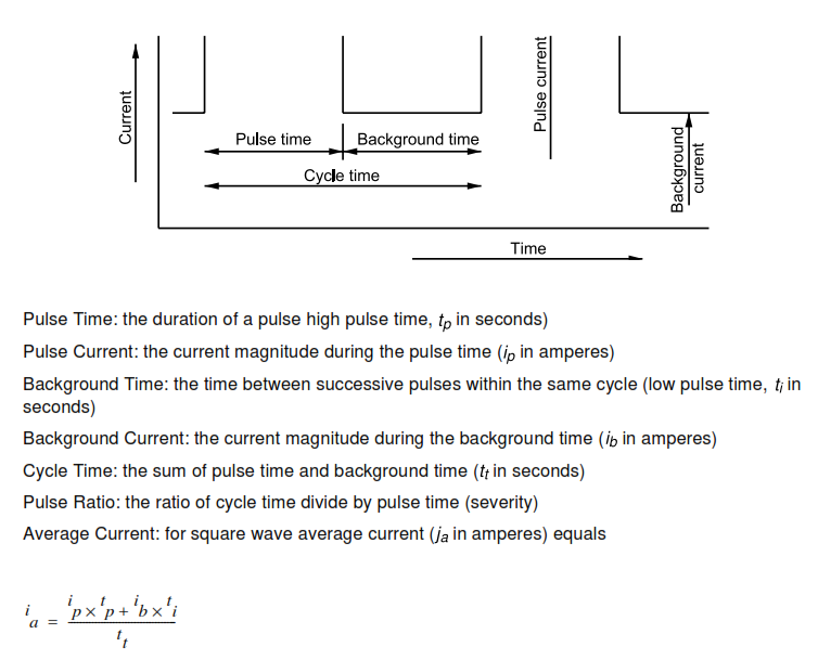
FIGURE 2 – Square-Edge Butt Joints
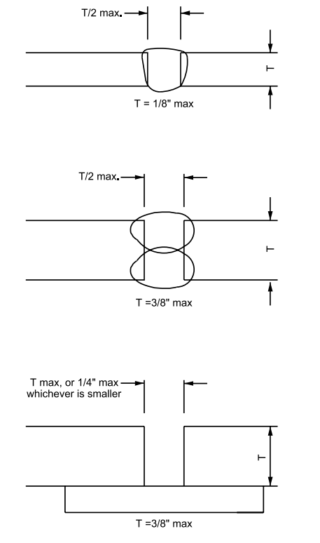
FIGURE 3 – Single-V Butt Joints
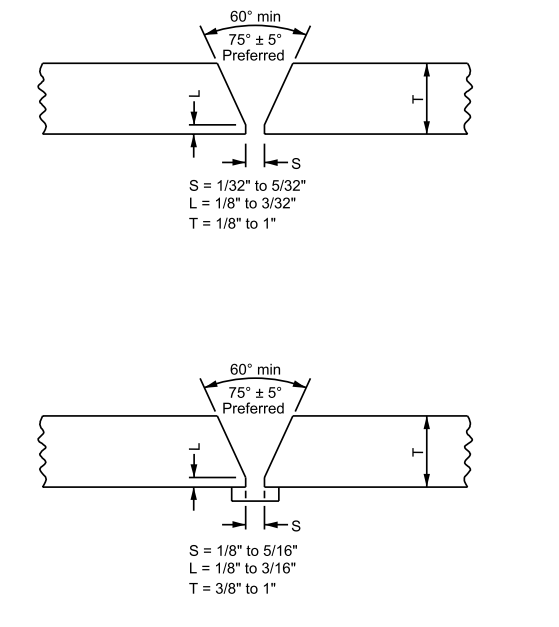
FIGURE 4 – Single-U and Double-U Joints
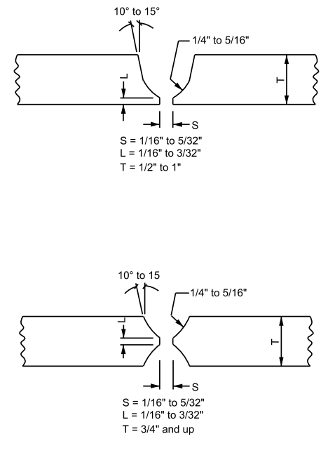
FIGURE 5 – Double-V Butt Joint
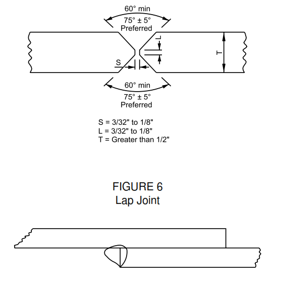
FIGURE 7 – Corner Joints
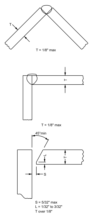
FIGURE 8 – Tee Joints
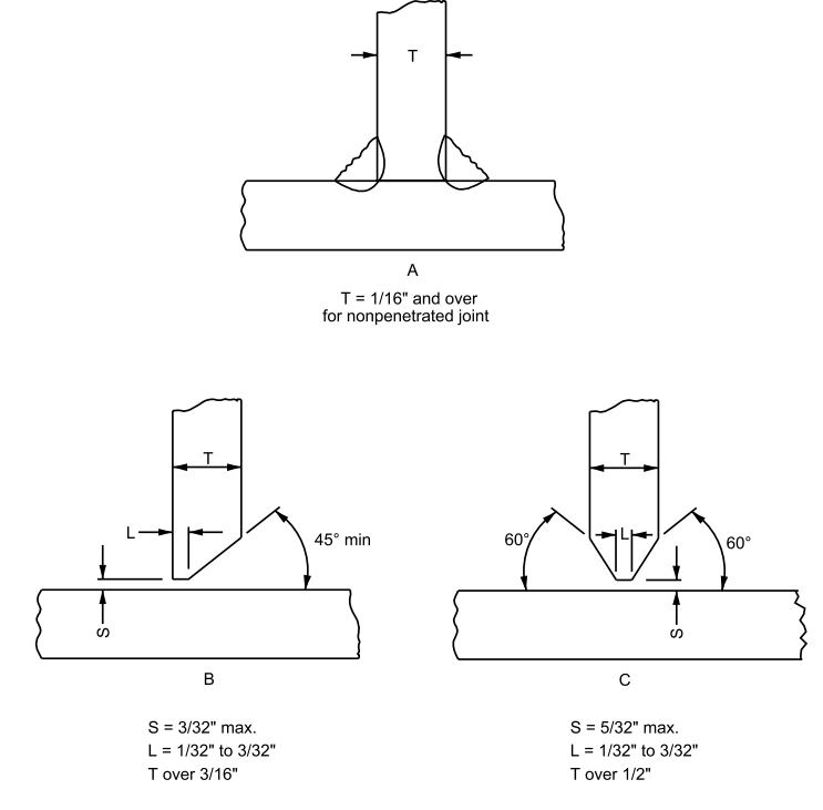
FIGURE 9 – Edge Joint
