Generator Uprating – Large Electrical Generators Troubleshooting
In general, old machines used to be conservatively designed, in particular the mechanic parts, such as the shaft, the pole body, and the frame. At the same time, the insulation materials were not as performing as those used in the present machines, and tend to cover a relatively large section of the stator slots. When a rewinding is decided, the Class F modern insulation thickness is much thinner than the existing ones. The extra space would be used to increase the copper cross section leading to a higher MW output.
In most cases, the existing over-designed shaft is able to take the new higher torque. Using the new computing capabilities and simulation tools, it is possible to push for a more tight and optimized design of both the electrical and the mechanical parts. The added value of an uprating could be pushed further by improving the ventilation arrangement. However, the uprating level is limited by the following considerations that will be discussed with more details in the following paragraphs:
Maximum MW available from the turbine shaft
Thermal limitation in the stator and rotor windings
Excitation system capacity
Turbine MW Output Limitation
The uprated generator output should take into account the turbine MW maximum capability. Ideally, the generator would have a rating that slightly exceeds the turbine output by a certain margin, usually 5 to 10%. Therefore, it is useless to invest for having a generator output that is much higher than what the turbine can supply. Another subfactor that should be considered is the efficiency. The maximum value of the turbine efficiency and generator efficiency don’t occur at the same load. Therefore, communication between generator and turbine engineers is essential to optimize the overall output and efficiency. Also, in order to avoid repetitive long shutdowns, plan to work on the upgrading of the turbine side and the generator at the same time.
Temperature Rise Limitation
When uprating the machine is planned, two major design criteria are to be considered. The first is the target level of the output increase, and the second is the expected new temperature rises in the stator and rotor winnings.
Stator Copper Cross Section Increase
When the stator core is to be replaced, the slot size could be increased to lodge more copper, but the saturation level of the stator yoke and the teeth are to be watched closely to avoid oversaturating them and adding constraints on the required field current.
If the original stator core is to be kept, the design of the new windings will be based on the existing slot dimensions. The copper cross section increase will depend on the quality of the insulation. With modern class F insulation systems, the overall insulation thickness is always less than that of the existing, and the difference will be taken by the copper. The optimal copper quantity will depend upon the existing temperature rise, and the acceptable limit levels for the uprated machine.
Stator Winding Temperature Rise Verfication
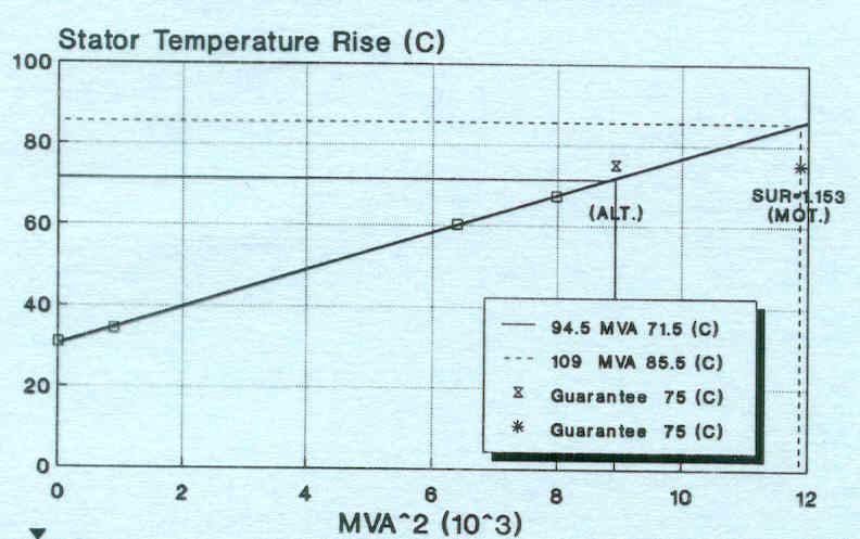
When the heat run test for the existing machine is available, we can draw the curve of the stator winding temperature rise as a function of the load MVA squared (MVA)² (or the stator current squared Is ²). As shown in the next figures, this curve is a straight line, where we can extrapolate the expected temperature rise corresponding to the uprated output, and compare it to the guaranteed value.
Field Current and Winding Temperature Rise Verification
When the generator output is increased, the required field current will be higher than that of the original rating. Therefore, two variables are to be checked: the excitation system capability, and the field temperature rise.
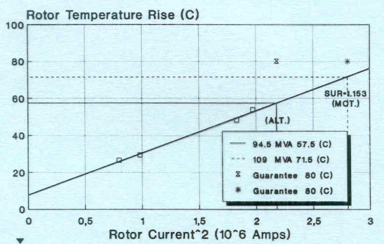
The expected temperature rise is estimated using an equivalent approach of the one used for the stator winding. We draw the straight line of the field temperature rise as a function of the field current squared (If²). Then we extrapolate the expected field temperature rise corresponding to the new output, and compare it to maximum acceptable limit allowed by the insulation system.

Figure 3 – Stator and Field Windings Temperature Limitation
Excitation System Limitation: Options for Uprating
As we mentioned previously, any uprating will involve an increase of the field current requirement, and the maximum excitation system current could be reached for lower values than the expected new rating. Three options are to be considered:
• Up-rating fixed by the maximum excitation current
• Increase the Power Factor
• Replace the existing excitation system
It is important to notice that an increase of the Power Factor will eventually limit the reactive power exchange. However, we know that many generators within Saudi Aramco facilities were designed for a low Power Factor of 0.8 or 0.85, while a value of 0.9 would be very acceptable. In all cases, the end user has to be consulted to make sure that this option will not hurt the plant operation.
For the old rotating exciters, when the excitation limit is major, we may consider re-insulating and up-rating the exciter itself. When economically justified, we can replace it with a new brushless or static excitation system, and benefit of the following advantages: no limitation on the up-rate, increased reliability, less maintenance, relatively low capital cost, and improved control possibilities.
Particularities Associated with Keeping or Replacing the Core
When the damage to the core is minor, it is usually sufficient to repair it by injecting a high quality insulating epoxy between the laminations, or to increase its rigidity by tightening the through bolts and the pressure end plates.
However, when the damage is major and reaches extended sections of the core, it might be a better option to replace the whole core. This will lead to the positive impact of having more control factors to further increase the copper quantity and the uprating level. Among these factors we can enumerate the following benefits:
• Possibility to redesign the number and dimensions of the slots, by enlarging the slot depth and/or width. When the number of slots is changed, we have to assure that we maintain the same number of turns per circuit per phase in order to obtain the same nominal voltage at the generator terminals.
• Optimizing the combination core-winding. T his may lead to a new winding configuration, as long as it is electrically equivalent to the existing one.
• Increase the efficiency by using laminations with higher permeability and lower W/kg core losses, new non-magnetic press plates and air duct spacers.
In all cases, whenever an uprating is planned, we need to check the saturation levels, in particular at the tips of the teeth and near the bottom corners of the slot.
Empirical Formulation
The winding temperature rise depends on the copper quantity in the slots (insulation thickness compromise) and the cooling configuration.
If we assume that the target temperature rise on the uprated winding will be kept equal to the existing temperature rise, then the copper cross section that is needed is:
S2 = S1 * (MVA2 / MVA1)² (1)
Where: S1: existing conductor cross section
S2: conductor cross section after up-rating
MVA1: existing MVA before uprating
MVA2: new MVA after uprating
For all cases, there will be a positive effect on the copper losses (R * I²), as they are inversely proportional to the conductor cross section.
R.I² = (Rho . L / S) . I² (2)
Where: R: resistance of the stator winding
I: nominal stator current
Rho: copper resistivity
L: total length of the copper
S: copper cross section
Another important characteristic to be checked, that is often specified by the generator owners, is the maximum dielectric strength expressed in kV/mm (or kV/mils) as:
G (dielectric strength) = Un / (√3 . Total Ground Insulation Thickness) (3)
Where: Un: nominal phase-to-phase voltage
The total ground insulation thickness includes: the ground insulation thickness, the turn insulation thickness, and the strand insulation thickness. When a maximum dielectric strength is specified, this means that the manufacturer has a minimum thickness of insulation to consider.
Nameplate Labeling
If the machine was redesigned, the original nameplate should remain on the unit and a new nameplate mounted adjacent to it with the word “redesigned” shown along with the new rating and date of the redesign. The original nameplate may be reversed with the black side out to prevent misinterpretation or confusion, in particular after long years and when the writings are not clear.
EXAMPLE:
Existing Winding:
4 parallel circuits per phase. Each coil has 6 turns having 2 x 4 strands
Dimensions of each strand: 2.286 mm x 6.35 mm
Cross section of the conductor = 2 x 4 [(2.286 x 6.35) – 0.5632] = 111.623 mm²
0.5632 mm² is the lost area corresponding to the rounded corners of the strand.
Net Cross section of the copper per coil = 669.7 mm²
New Winding:
Let’s assume that the new winding will have 3 turns per coil, having 2 x 10 strands.
Dimension of each strand: 7.90 mm x 2.17 mm.
To be electrically equivalent to the existing, the new winding will have only 2 circuits per phase.
Cross section of the conductor = 2 x 10 [(7.90 x 2.17) – 0.5632] = 331.596 mm²
Cross section of the copper per coil = 994.8 mm²
Output increase: √ (994.8 / 669.7) = 1.22
Uprating in percent: 22%
The new generator will have an output that is 22% higher than the existing.
