1 Introduction
2 References
3 Definition
4 Why We Need Grounding System?
5 Parameters Affecting Grounding Grid Design
6 Step by Step Design Procedure
Ground Grid Design Guidelines
1. Introduction to Ground Grid Design
The main purpose of this article is to provide ground grid design guidelines and introduce step by step procedure to calculate, step and touch voltages and ground potential rise (GPR). This is not intended as grounding tutorial however it does contain information that will provide a basic understanding of how to design ground grid.
2. Ground Grid References
2.2 Industry Codes and Standards
Institute of Electrical and Electronics Engineers
ANSI/IEEE 80 – Guide for Safety in AC Substation Grounding
IEEE 80 – Guide for Safety in AC Substation Grounding
IEEE 81 – Guide for Measuring Earth Resistivity, Ground Impedance and Earth Surface Potentials of a Ground System
IEEE 487 – Recommended Practice for the Protection of Wire-Line Communication Facilities Serving Electric Supply Locations
ANSI/IEEE 367 – Recommended Practice for Determining the Electric Power Electric Power Station Ground Potential Rise and Induced Voltage from a Power Fault
ANSI/IEEE 1100 – Recommended Practice for Powering and Grounding Electronic Equipment
National Fire Protection Association
NFPA 70 (NEC 250) – National Electric Code, Article 250
3. Ground Grid Definition
Ground potential rise (GPR): The maximum electrical potential that a substation grounding grid may attain relative to a distant grounding point assumed to be at the potential of remote earth. This voltage, GPR, is equal to the maximum grid current times the grid resistance.
Step Voltage: The difference in surface potential experienced by a person bridging a distance of 1 m with the feet without contacting any grounded object.
Touch voltage: The potential difference between the ground potential rise (GPR) and the surface potential at the point where a person is standing while at the same time having a hand in contact with a grounded structure.
Transferred voltage: A special case of the touch voltage where a voltage is transferred into or out of the substation from or to a remote point external to the substation site.
IG: Net fault current flowing through the grid to the earth
RG: ground grid resistance to remote ground
Surge Protective Device: designed to protect electrical devices from voltage spikes. A surge protector attempts to limit the voltage supplied to an electric device by either blocking or by shorting to ground any unwanted voltages above a safe threshold.
Potential gradient: The change of voltage over distance.
Mesh potential: The maximum touch voltage within a mesh of a ground grid.
Grounding Grid: A system of horizontal ground electrodes that consists of a number of interconnected, bare conductors buried in the earth, providing a common ground for electrical devices or metallic structures, usually in one specific location.
Grounding system: Comprises all interconnected grounding facilities in a specific area.
Grounding Electrode: conductor specifically makes contact with the earth for grounding a power system
Ground Mat: A solid metallic plate or a system of closely spaced bare conductors that are connected to and often placed in shallow depths above a ground grid or elsewhere at the earth surface, in order to obtain an extra protective measure minimizing the danger of the exposure to high step or touch voltages in a critical operating area or places that are frequently used by people. Grounded metal gratings placed on or above the soil surface, or wire mesh placed directly under the surface material, are common forms of a ground mat.
Bonding: The permanent joining of metallic parts to form an electrically conductive path that will assure electrical continuity and the capacity to safely conduct current likely to be imposed.
Zone of Influence: The area surrounding the electric supply location that is raised in potential above a remote (or true) earthling point is referred to as the GPR zone of influence. In practice, 300 V is often used as the boundary of this zone of influence. For a more complete discussion on this topic, refer to IEEE Std 367-1996.
4. Why We Need Grounding System?
There are four main reasons why grounding system is required:
Personnel Safety: to protect the personnel from electric shock by ensuring that, under fault conditions, all surfaces with which a person is in simultaneous contact, including those of metallic equipment and the ground, remain at safe potentials.
Equipment Safety: to safeguard electrical equipment by grounding power systems to ensure that, under fault conditions, both voltages and currents are within predictable limits and that the protective devices will operate reliably and with appropriate discrimination.
Lightening Protection: to provide a path to ground for current when lightning arresters operate due to direct lightning strikes, to lightning induced surges, or to switching surges.
Electrostatic Control: to reduce the possibility of static electricity discharge that would present a fire risk in hazardous areas.
Grounding systems are not meant to last forever; they are affected by the environment they are installed in, for this reason inspection and integrity check of the system should take place every few years.
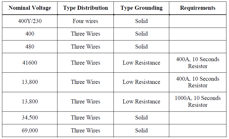
There are different types of grounding systems, grounding requirements differ based on the voltage level, Table 1 below summarizes system grounding requirements.
Table 1 – Grounding Type Requirements
5. Parameters Affecting Grounding Grid Design
Soil resistivity, grid depth, wire sizing, number of installed rods, area of the grid and allowable fault time are all parameteres affecting the design of the ground grid and contribute to its optimzation. The subparagraphs below provide the reader with basic concept of the subject parameteres and help understand further calculations.
a) Soil Resistivity and Method of Measurement
The grid resistance and the voltage gradient within a substation are directly dependent on the soil resistivity of the upper layer (see Figure 1 below). Measuring soil resistivity could be misleading if not following the accurate method and collecting enough data.
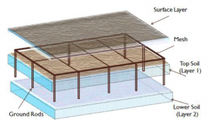
Figure 1 – Soil Layers and Ground Grid Overview
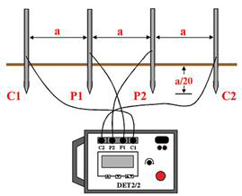
There are many methods to measure earth resistivity, it allow two methods of measurement: the four-point method (Wenner method – See Figure 2) and the non-contacting ground resistivity mapping instrument (Geonics or equal). These methods are most recommended in the industry. For Wenner method, small electrodes are buried in four small holes in the earth, all at an equal depth and spaced (in a straight line) at intervals a. Current is injected passed between the two outer electrodes and the potential “V” between the two inner electrodes is measured with a potentiometer or high-impedance voltmeter. Then, “V/I” ratio gives the resistance “R” in ohms.
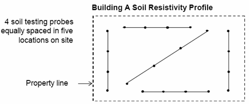
The interpretation of the measured data is very critical, to avoid errors and outliers it is recommended to conduct measurement across the five sides as indicated in Figure 3 and to average the data. For more information, please refer to IEEE 81.
b) Grid Depth and Number of Ground Rods
The depth of the grid is another factor affecting the design, SAES-P-111 requires that ground grids are to be buried to a minimum depth of 460 mm (18 in.) or 0.5m. A longer length of cables used in the grid reduces the step and touch voltages and the grid resistance.
The physical conditions of the substation dictate the number and the length of the ground rods vs. the conductor grid length. The ground rods are normally installed at the perimeter of the grid to moderate the increase of the surface gradient that is near the peripheral meshes. Ground rods should also be installed at major equipment and especially at lightning arresters.
c) Wire Sizing
Under fault conditions, all of the heat is assumed to be retained in the conductor. Because little time is available to dissipate the heat, the fusing temperature of the conductor, the temperature limit of the connections, and the physical strength of conductors need to be carefully evaluated to determine the conductor size. The latter must relate to the current/time rating of the neutral grounding device, subject to a minimum size of 780 mm² (No. 2/0 AWG) for mechanical robustness.
d) Fault Times
Fault time is the duration of time that the fault current flows before being interrupted. Saudi Aramco standard (SAES-P-111) requires maximum 0.5 second time to interrupt the occurring fault.
6. Step by Step Design Procedure of Ground Grid
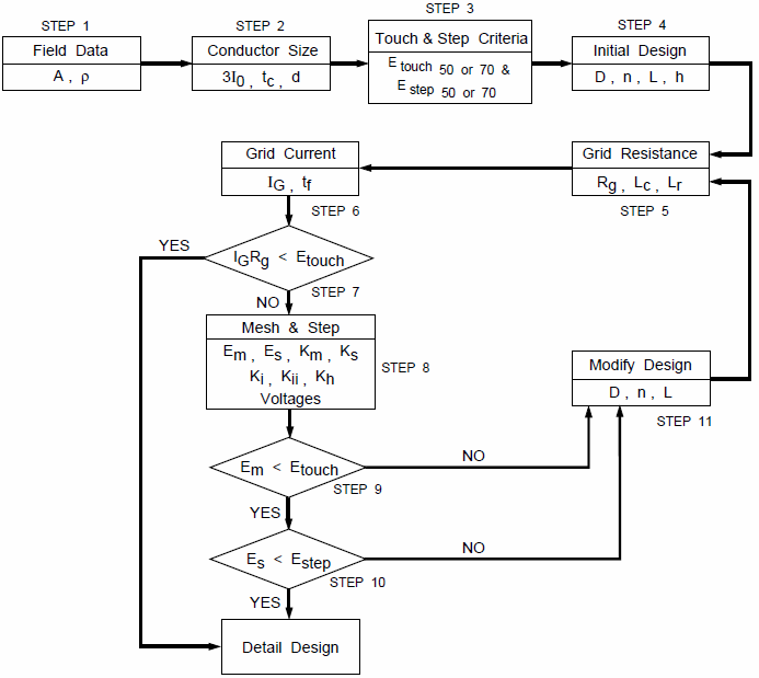
The block diagram illustrated in Figure 4 below demonstrates a step by step procedure to design ground grid. Formulas, instructions and explanations are followed to describe all required details. It worth to mention that a computer analysis and calculation is also allowed, however the herewith procedure helps the designer to understand the concept and give the manual calculation tool if desired.
The known information includes the following:
Substation length 100 m
Substation width 70 m
Substation soil resistance test results = 1.587 ohms
Earth tester probe spacing 15
Buried depth of ground grid 0.48 m~0.5 (18”)
Power system RMS symmetrical ground fault current is 7,500 amp
Current division factor is 0.48
Decrement factor is 1.00265
Incoming substation voltage 115 kV
nA- Number of parallel conductors on the shorter side. 21 each 100 m
nB Number of parallel conductors on the longer side. 15 each 70 m
No future growth possibility
Please Check following document for all calculation of Step by Step Ground Grid Design Procedure.
Step by Step Ground Grid Design Procedure