HDPE Blending silo Load Sensor calibration procedure
- The silo which is going to be calibrate should be fully emptied.
- Check conditions before, around the load cells for related silo.
( Are they clean and the sensing surfaces of the load cells are touching to the silo.)
- Open the load cell front control panel near the silo. ( See figure-1)

- Change the jumper position from close to open. ( Remove it)

( Releases the load cell transmitter for to calibrate. ( See figure-2)
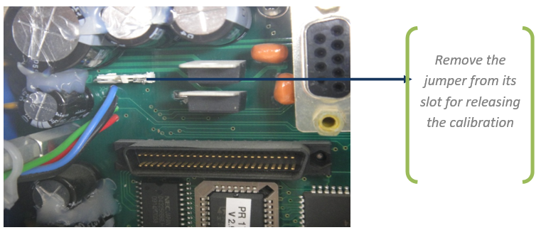
After completing your calibration job put the jumper into original position.
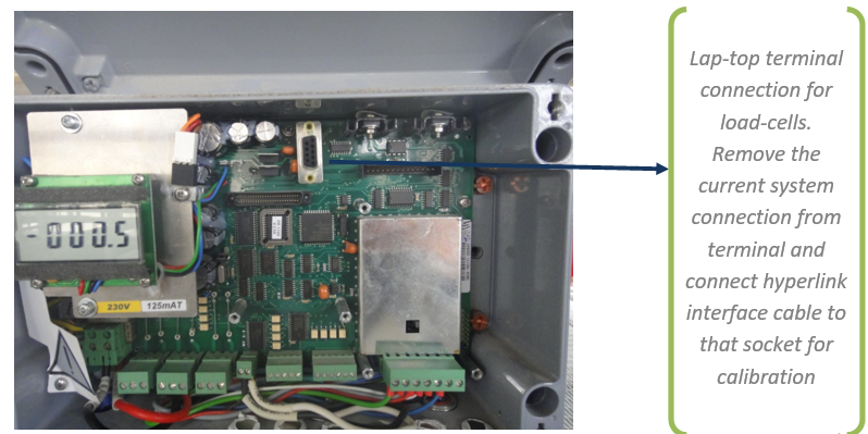
- Connect the lap-top to load cell transmitter terminal by interface cable.
( See figure-3 )
- Run hyper terminal software from the lap-top.
- After running the hyper terminal software insert necessary communication settings.
- In hyperlink software double click the phone icon and open the software.
(Software Items are coming sequentially)
- Enter to ‘’Configuration’’
- Set the analog output values in below before starting the calibration.
- Select ‘’Analog output ‘’
- Below gross zero = 4mA
- Above gross FSD = 20mA
- Value at 4 mA = 0.0 t
- Value at 20 mA = 500 t
- Go to ‘’Calibration’’
- Start-up ‘‘New calibration’’
- Enter ‘’ Full Scale’’
- Set the silo as full range for ‘’500.0 t’’
- Select ‘’ Step width to 5’’
- Set dead load ‘’ with current load’’
- Select ‘’Calculate span with load cell data’’
- Enter the ‘’Number of load cells in the system’’ ( # 4 for each blending silo )
- Enter ‘’Nominal Load data” as 125 t
- Enter ‘’ Gravity of location constant’’ as 7933
- Select ‘’Exit’’in
- Select ‘’ Accept data in calculate span’’
- Select ‘’ End Calibration ‘’
- Save and disconnect from the terminal.
- After finishing your job not to forget to put in jumper original position.
- Remove hyperlink interface cable from terminal and connect system cable to terminal.
- Close the panel door.
Like!! Thank you for publishing this awesome article.