Heat exchangers transfer heat between hot and cold fluids using a metal wall. They work by conduction and forced convection. There are several types used by plants and refineries:
- Shell and tube heat exchangers: Hot and cold fluids flow through tubes inside a shell. Heat transfers through the tube walls.
- Air-cooled heat exchangers: These use air to cool hot fluids. Fins or tubes are exposed to air flow, cooling the fluid inside.
- Double-pipe heat exchangers: Consist of two concentric pipes. One carries hot fluid, and the other carries cold. Heat transfers between them.
- Plate-and-frame heat exchangers: Consist of plates with fluid passages. Hot and cold fluids flow in alternating channels, transferring heat through the plates.
Cooling towers and process furnaces are other types of heat transfer equipment used by industries, but they’re not discussed here. Cooling towers cool water through evaporation, while process furnaces transfer heat via radiation.
TEMA-Type Shell and Tube Heat Exchangers.
A shell and tube heat exchanger is a common type of heat exchanger used in industrial settings. It consists of a metal shell enclosing a set of tubes arranged in parallel. One fluid, called the tubeside fluid, flows inside the tubes, while the other fluid, called the shellside fluid, flows outside the tubes within the shell. Both the shell and the tubes are designed to withstand specific pressures.
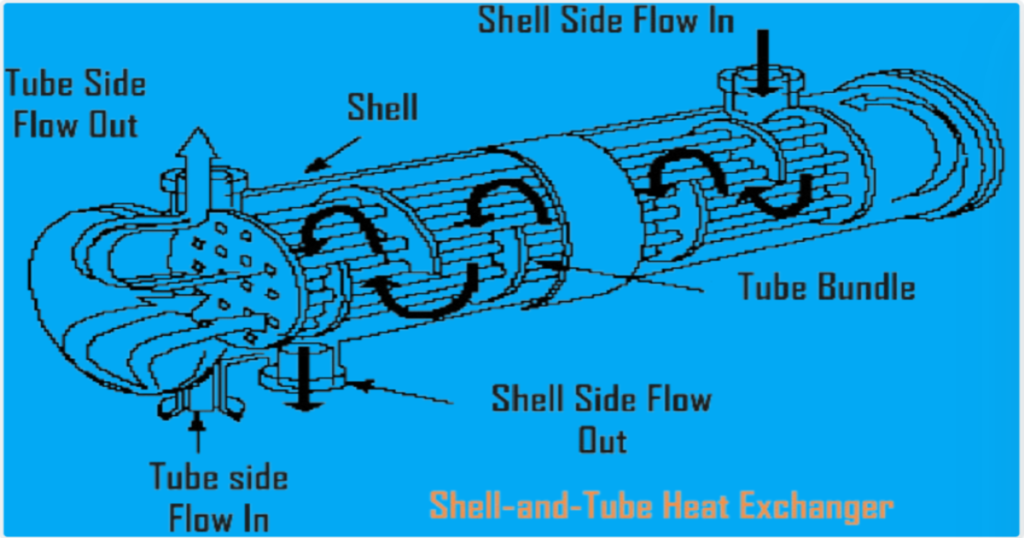
TEMA, which stands for the Tubular Exchanger Manufacturers Association, is an association of companies that manufacture these types of heat exchangers. They have developed engineering standards that govern the design of shell and tube heat exchangers, ensuring they meet specific requirements for efficiency, safety, and durability. When a heat exchanger is referred to as a “TEMA-type shell and tube heat exchanger,” it means it’s designed according to TEMA standards.
Design Standards.
Heat exchangers, including shell and tube types, are typically constructed in accordance with pressure vessel codes to ensure their safety and reliability. Most plants and refineries adhere to American standards and mandates compliance with the American Society of Mechanical Engineers (ASME) Boiler and Pressure Vessel Code, Section VIII, Division 1 or 2. This alignment with ASME standards guarantees that equipment undergoes rigorous design, fabrication, inspection, and testing processes according to widely accepted industry norms.
While ASME codes provide a foundational framework, they may not offer sufficient specificity for the diverse array of heat exchanger applications. To address this, industry-specific standards have been developed. The Tubular Exchanger Manufacturer’s Association (TEMA) standard, titled “Standards of the Tubular Exchanger Manufacturer’s Association,” sets guidelines for shell and tube heat exchangers across various industries, including petroleum. Additionally, the American Petroleum Institute (API) has issued API Standard 660, which focuses on shell and tube heat exchangers for general refinery service. These standards serve to clarify design requirements and ensure consistency and safety in heat exchanger fabrication and operation within specific industrial contexts.
TEMA Classifications.
The TEMA Standard 7th Edition (1988) classifies shell and tube heat exchangers into three categories based on the severity of the service environments they will operate in: Classes R, C, and B.
- TEMA Class R: This classification is tailored for severe service environments found in petroleum refineries and related industries. Class R heat exchangers are engineered with robust design and fabrication requirements, prioritizing durability and safety. They are typically selected for applications where reliability is paramount due to harsh operating conditions.
- TEMA Class C: Class C heat exchangers are designed for generally moderate service environments commonly encountered in commercial and general process industries. They are engineered with a focus on achieving maximum economy and compactness while still meeting moderate safety and service requirements. Class C heat exchangers are chosen for applications where the operating conditions are less severe compared to Class R but still require reliable performance.
- TEMA Class B: Class B heat exchangers are specified for use in the chemical process industry. While they share some design requirements with Class R, they are closer in terms of minimum thickness and corrosion allowance to Class C. Class B heat exchangers are suitable for applications where the service conditions are not as severe as those in petroleum refining but still require robust design and fabrication to withstand chemical processes.
Most shell and tube heat exchangers used are Class R, particularly for applications where durability and safety are critical. However, there are instances where less expensive Class C exchangers may be suitable, such as for nonhydrocarbon services, lubricant, and seal oil coolers included in standard packaged units, as indicated in SAES-E-004, Para. 7.5.1.
| Design Item | Class/Service |
| R/Refinery | C/General | B/Chemical | |
| Corrosion Allowance (carbon steel). | 1/8 in. | 1/16 in. | 1/16 in. |
| Minimum Thickness of Shell. | See Table R-3.13 | See Table CB-3.13 | See Table CB-3.13 |
| Minimum Tie-Rod Diameter. | 3/8 in. | 1/4 in. | 1/4 in. |
| Gasket Contact-Surface Tolerance. | ±1/32 in., max. | None | None |
| Minimum Bolt Size. | 3/4 in. | 1/2 in. | 5/8 in. |
TEMA Designations.
The TEMA designation system for shell and tube heat exchangers is widely used in industries like petroleum refining and chemical processing to specify exchanger sizes and types. It consists of a two-part size designator and a three-letter type designator.
TEMA Size Designation.
- The size designator comprises two numbers separated by a hyphen (-).
- The first number indicates the nominal shell diameter in inches, rounded to the nearest integer.
- The second number indicates the nominal tube length in inches.
- Following the size designator are three letters indicating the front-end type, shell type, and rear-end type of the heat exchanger. For instance, in the example ’23-192-AES’, ‘AES’ signifies a front-end type A, a shell type E, and a rear-end type S.
Note: The designation method for certain types of heat exchangers, such as kettle-type reboilers, may deviate from this format. Refer to the TEMA standard for specific details.
TEMA Type Designation.
- The TEMA type designation consists of three letters.
- The first letter describes the heat exchanger’s front-end or stationary head type, chosen from five types.
- The second letter describes the shell type, chosen from seven types. This letter may be omitted if the specification pertains only to the purchase of replacement tube bundles.
- The third letter describes the rear-end or floating-head type, chosen from eight types.
These designations help standardize the identification of heat exchangers, facilitating communication and ensuring clarity in specifications and proposals.
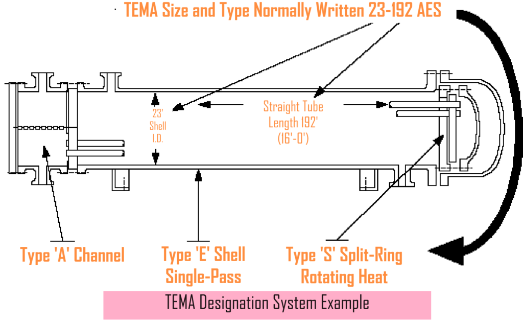
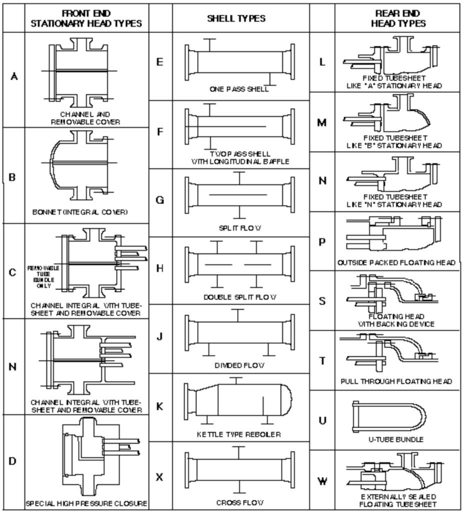
Figure 4. TEMA Figure N-1.2
Considerations for Selecting Exchanger Component Options.
Here are the considerations for selecting the appropriate stationary head type, shell design, and rear end for shell and tube heat exchangers:
| Type | Description | Selection Consideration |
| Selection Considerations for Stationary Heads. | ||
| A | Channel and Removable Cover | The most common type of head that is used in shelland-tube heat exchangers. Used with fixed tubesheet, U-tube, and floating head exchangers. In most cases, the bundle is removable for mechanical cleaning. |
| B | Bonnet or Removable Channel with Integral Cover | Normally used only for low-fouling tubeside services. Used with fixed tubesheet, U-tube, and floating head exchangers. Less expensive than Type A head. |
| C | Channel Integral with Tubesheet and Removable Cover | Used with some types of fixed tubesheet exchangers and reboilers. |
| N | Channel Integral with Tubesheet, Shell, and Removable Cover | Shellside fluid must be relatively low-fouling so that chemical cleaning can be used. Not recommended for use with U-tube or floating head exchangers because of maintenance difficulties. |
| D | Special High Pressure Closure | Special high pressure head that is used when the tubeside design pressure exceeds approximately 10 340 kPa (1 500 psi). |
| Selection Considerations for Shell Designs. | ||
| E | Single Pass | The most common shell design. |
| F | Two Pass | Two pass affords slightly better heat transfer than single pass because two passes on the shell side more closely approximates counter-current flow. In order to avoid an excessively thick longitudinal baffle, two pass should not be used with a shellside pressure drop greater than approximately 70 kPa (10 psi). Shellside temperature range should be limited to 175°C (350°F) to avoid both excessive heat leakage through the baffle and thermal stress in the baffle, the shell, and the tubesheet. |
| G | Split Flow | Typically used in condensing and boiling services to reduce pressure drop and to enhance heat transfer duty. |
| H | Double Split Flow | Same as above. |
| J | Divided Flow Shell | Same as above. |
| X | Cross Flow | Same as above. |
| K | Kettle-Type Reboiler | Typically used for boiling/vaporizing services. The large shell promotes heat transfer and vapor disengagement. |
Here are the selection considerations for specific types of stationary heads and rear ends in shell and tube heat exchangers:
Stationary Head Type:
- Type L: Used with fixed tubesheet exchangers when mechanical cleaning of tubes is required.
- Types M and N: Utilized with fixed tubesheet exchangers when chemical cleaning of tubes is possible.
- Type P: Not recommended due to the tendency of packed joints to leak, particularly unsuitable for shellside hydrocarbons or toxic fluids.
- Types S and T: Designed for removable bundle configurations. Type S features a floating head with a split backing ring to reduce shell diameter requirements, while Type T allows for easier bundle removal, preferred for maintenance.
- Type U: Used with U-tube bundles where mechanical cleaning of the tubeside is unnecessary. Typically, a formed head is used on the shell, although a bonnet-type head can also be used.
- Type W: Uses a packed joint to separate the tubeside and shellside fluids, but not recommended due to the tendency to leak.
Selection Considerations for Rear Ends.
The specific considerations for rear end selection are not provided in the given text. However, factors to consider may include ease of maintenance, compatibility with service conditions, and any special requirements for bundle removal or cleaning procedures.
TEMA Component Nomenclature.
TEMA provides standard terminology for the components of shell and tube heat exchangers, outlined in Section N of the TEMA Standard. Here are some key terms:
1. Baffle Type.
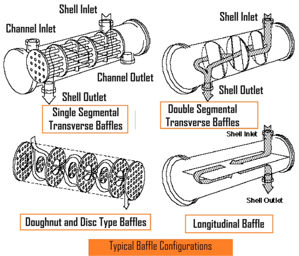
Baffles are installed on the shellside of heat exchangers to direct the flow of shellside fluid across the tubes in a specific pattern, enhancing heat transfer. They can be oriented either transversely (perpendicular to the axis of the heat exchanger) or longitudinally (parallel to the axis of the heat exchanger).
- Transverse Baffles: These include segmental and “doughnut and disk” baffles, illustrated in Figure 8.
- Segmental Baffles: These can be single, double, or triple segmental. Single segmental baffles have one fluid passage cut through them, while double and triple segmental baffles have two and three passages, respectively. They may be cut horizontally or vertically.
- No Tube in the Window Design: In some cases, such as when tube vibration is a concern, this design is used. It arranges the tube bundle so that there are no tubes located in the window of the baffle, where a particular baffle does not support the tubes. This ensures that every tube is supported by each baffle, increasing the lowest mechanical natural frequency of the tube bundle. However, this design requires a larger shell size because more tubes are needed to achieve the necessary heat transfer.
2. Bundle (or Tube Bundle).
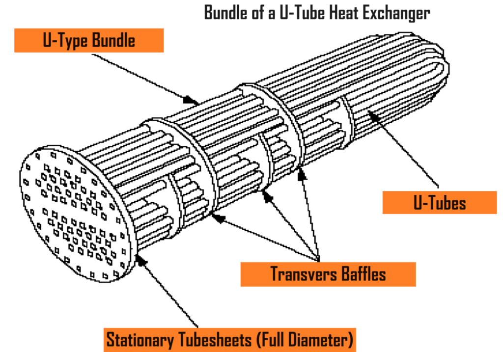
The “bundle” in a heat exchanger with removable bundles includes the tubesheet (or tubesheets), tubes, baffles and/or supports, tie-rods, and spacers. In a straight-tube, split-ring, floating-head-type heat exchanger, the bundle is depicted in Figure 9. For a U-tube heat exchanger, the bundle is illustrated in Figure 10. In fixed tubesheet exchangers, the bundle refers to the part extending from tubesheet to tubesheet, excluding channels and bonnets.

3. Tube cleaning lanes.
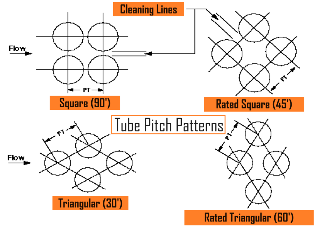
Tube cleaning lanes are the spaces between rows of tubes in a removable-bundle heat exchanger. These lanes are wide enough to allow brushes and other cleaning devices, like hydroblast equipment, to enter. They’re typically provided when tubes are arranged in square or rotated square pitches, as shown in Figure 11.
4. Tube pitch pattern.
The tube pitch pattern describes how tubes are arranged as they penetrate the tubesheets, baffles, and supports. Common pitch patterns include square, rotated square, and two types of triangular arrangements: one with flow parallel to the base of an equilateral triangle and another with flow entering at the apex of the triangle. These patterns, illustrated in Figure 11, influence the heat exchanger’s efficiency and ease of maintenance.
5. Tubeside passes.
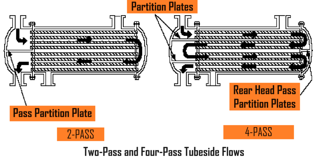
Tubeside passes indicate how many times the fluid flows from one end of the bundle to the other. In heat exchangers with multiple tubeside passes, several tubes are grouped together within the channel. Pass partition plates, separating these tube groups, are situated in the channel. Sometimes, pass partition plates are also found in the floating head, depending on the number of tubeside passes needed. Each group of tubes in a pass receives the entire flow from the heat exchanger’s inlet. Figure 12 depicts designs for two-pass and four-pass tubeside heat exchangers.
Types of TEMA Shell and Tube Heat Exchangers.
This section discusses the primary types of shell and tube heat exchangers that are installed in plant facilities. These types include the following:
- Split-Ring Floating Head.
- Pull-Through Floating Head.
- U-Tube.
- Kettle-Type.
- Fixed Tubesheet.
- Special High Pressure.
- Double Tubesheet.
Split-Ring Floating Head (TEMA-Type AES).
- To remove the tube bundle, the shell head, floating head cover, and split-ring backing device must be removed.
- A standard TEMA-Type AES exchanger is illustrated in Figure N-2 of the TEMA Standard.
Pull-Through Floating Head (TEMA-Type AET).
- TEMA-Type AET heat exchangers have pull-through floating head tube bundles.
- They are the current standard design used in most plant facilities.
- The shell is slightly larger and more expensive than the AES shell.
- Unlike the AES design, it is not necessary to disassemble the shell cover and floating head to remove the bundle from the shell.
- This design reduces field maintenance and turnaround time.
These descriptions provide an overview of the two types of shell and tube heat exchangers, highlighting their differences and applications within plant facilities.

U-Tube Kettle Reboilers, such as the TEMA-Type AKU and BKU, are commonly utilized for various applications, including steam services. Here’s an overview of each type:
TEMA-Type AKU.
- This kettle reboiler features a removable channel cover.
- It is suitable for applications where easy access to the channel is required for maintenance or cleaning purposes.
TEMA-Type BKU.
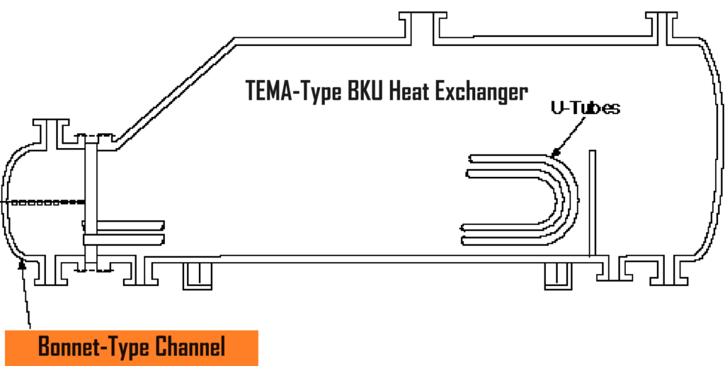
- The BKU kettle reboiler, as illustrated in Figure 14, is equipped with an integral welded channel cover.
- It is preferred for applications where the tubeside fluid is clean, such as steam services.
- The BKU design is also chosen when minimizing heat loss to the atmosphere is necessary.
- The entire bonnet channel can be insulated to conserve heat, making it an efficient choice for processes requiring heat retention.
These U-tube kettle reboilers provide reliable performance in various industrial processes, offering options for accessibility, cleanliness, and thermal efficiency based on specific operational requirements.
Pull-Through Kettle-Type (TEMA-Type AKT).
- These kettle-type reboilers feature pull-through floating heads.
- The AKT is typically employed in situations where excessive fouling on the tubeside necessitates mechanical cleaning inside the tube bundle.
- The design and specifications for the AKT heat exchanger can be found in Figure N-2 of the TEMA Standard.
Fixed Tubesheet (TEMA-Type BEM).
- TEMA-type BEM exchangers are equipped with bonnet heads on both channels.
- Commonly utilized in a single tube pass arrangement, particularly as a vertical thermosyphon reboiler.
- The tubesheets are integrally welded to the shell.
- In instances where temperature differences between the tubes and the shell exceed 30°C (50°F), an expansion joint in the shell may be necessary.
- Figure N-2 of the TEMA Standard illustrates a BEM-type exchanger with a modified conical rear head.
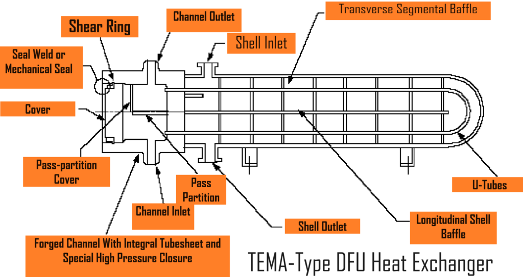
Special High Pressure U-Tube (TEMA-Type DFU).
- These heat exchangers, illustrated in Figure 15, are equipped with special high-pressure closures on the channel (or tube) side.
- The DFU type is employed when the tubeside pressure reaches approximately 10,340 kPa (1,500 psi) or higher.
- Typically, the channel is made from a forged steel ring, with the tubesheet usually welded to the channel.
- The channel cover is designed with a shear-key ring, held in place by a key backing ring flange bolted to the channel.
- Many high-pressure closures incorporate proprietary designs from manufacturers.
A double tubesheet design employs two tubesheets to separate the tubeside and shellside fluids, with the tubes passing through both sheets. This construction is utilized in applications with exceptionally high tubeside pressures or where any fluid leakage between the two sides is intolerable. Various manufacturers offer proprietary designs for double tubesheet configurations, ensuring stringent safety and operational requirements are met.