1. SCOPE
2. PURPOSE
3. DEFINITION
4. REFERENCE
5. INSULATION TERMINOLOGY
6. RESPONSIBILITIES
7. HANDLING & STORAGE
8. MATERIALS
9. WORK FLOW CHART
10. PRE APPLICATION PREPARATION
11. INSULATION PROCEDURE
12. TML PLUG INSTALLATION
13. DRESS UP INSULATION WORK
14. REPAIR WORK PROCEDURE
15. QUALITY CONTROL
16. HEALTH, SAFETY ENVIRONMENT
17. ATTACHMENTS (INSULATION DRAWINGS&JSA)
1. SCOPE:
This Method Statement cover requirements for Hot and Cold Insulation works for piping and equipment, storage and handling of insulation materials, quality control, insulation materials as per specification, application of insulation and all safety aspects pertaining insulation activity for plants, buildings and refineries.
2. PURPOSE:
The purpose of this Method Statement is for Hot and Cold Insulation of Piping and Equipment. The Hot Insulation is designed to control the heat loss for heat conservation and use to protect the personnel from hot surfaces. The Cold Insulation reduce the transfer of heat to piping and avoid condensation and icing on exterior surfaces and personnel protection.
3. DEFINITION:
The following terms will be used in the method of statement hereafter,
COMPANY :
CONTRACTOR :
SUBCONTRACTOR :
4. REFERENCES:
This method statement referred to the latest issue of standards as well as general Specification listed below,
SAES-N-001 : Engineering Standard for Basic Criteria Industrial Insulation.
SAES-A-105 : Noise Control.
S-000-1390-001 : General Specification for Insulation.
SATIP-N-001 : Saudi Aramco Test Inspection Plan for cold service.
SATIP-N-002 : Saudi Aramco Test Inspection Plan for hot service.
AA-036911-001 : Insulation Details for Hot Piping.
AA-036912-001 : Insulation Details for Hot Vessels.
AA-036913-001 : Insulation Details for Cold Piping.
AA-036913-002 : Insulation Details for Cold Vessels.
PIP INEG 1000 : Insulation Design and Type Codes.
PIP INEG 2000 : Guideline for use of Insulation Practices.
PIP INGG 1000 : Insulation Document use Guideline.
PIP INIC 1000 : Cold Insulation Installation Details.
PIP INIH 1000 : Hot insulation Installation details.
PIP INSA 1000 : Acoustic Insulation Systems Specification.
PIP INSC 1000 : Cold Service Materials and Installation Specification.
PIP INSC 2000 : Installation of cold service Insulation System.
PIP INSH 1000 : Hot Service Materials and Installation Specification.
PIP INSH 2000 : Installation of hot service Insulation System.
PIP INSR 1000 : Installation of Flexible/Removable Insulation covers.
PIP INTG 1000 : Insulation Inspection Checklist.
5. INSULATION TERMINOLOGY:
The Subcontractor will use the following Company terms of Insulation as per s Specification.
Heat conservation Insulation (EC)
Personal Protection Insulation (PP)
Cold Service Insulation (C)
Electric Traced Insulation (ET)
Steam Traced Insulation (ST)
Acoustic Control Insulation (A+A,B,C)
5.1 EC- (Heat conservation Insulation)
Heat conservation insulation shall be designated with EC. The primary consideration For using EC shall be economics. It is applied to prevent escape of thermal energy from process equipment & piping.
5.2 PP- (Personal Protection Insulation)
Personal protection shall be designated with code PP. The primary consideration for Using PP insulation shall be to limit the temperature of exposed surfaces and to Protect personal injuries.
5.3 C- (Cold Service Insulation)
Cold service insulation shall be designated with code C. The primary consideration For using cold service insulation shall be based on maximum allowable heat gain. The Design of cold insulation shall be based on control of heat gain and limiting surface Consideration when the operating temperature is below ambient.
6. RESPONSIBILITIES:
Project Manager:
i) Overall in-charge of the project and controls all Construction, QC Work Activities including HSE compliance for the entire project
ii) Shall be responsible to provide his team with the appropriate resources to ensure that all works are done in accordance with the project quality requirements
Site Engineer:
i) Shall be responsible for the overall implementation of the works governing this procedure.
ii) Shall be responsible for establishment of construction organization, monitoring job quality, schedule control and overall project management.
QC Manager:
i) Assures full implementation of required quality requirements and maintains the required documentation as per Saudi Aramco SATIP-N-001-01/02 for final acceptance and handover of documents
ii) Keeping log of all inspection activities, NCR status and other activities QC Manager is to ensure QC Inspectors are familiar with this procedure, the applicable Quality Control Procedure including Saudi Aramco SATIP-N-001-01/02 and SAUDI ARAMCO Safety requirements of the activities.
iii) He will coordinate with authorized QA/QC representative of client.
QC Inspector:
i) Shall be responsible for overall control and field inspection and preparation of inspection reports related to this procedure.
ii) He will carry out the required inspections and prepare QC documents/QC reports in accordance with the approved ITP (Inspection and Test Plan).
Insulation Supervisor:
i) Shall be responsible for execution and implementation of all site activities related to this procedure.
ii) Shall fill out a log on a daily basis, recording all problem areas, delays, non-compliances and corrective actions.
Storekeeper:
i) Shall be responsible for the materials receiving, handling, storage, preservation, issuance and maintaining quality and safety of the products as well as environment.
Safety Supervisor:
i) Shall be responsible for implementation of safety and health of personnel related to this procedure.
ii) Shall be responsible for all works to be carried out as per project safety plan.
7. HANDLING & STORAGE:
i) Internal inspection of the storage area is to be done prior to stock and also shall be approved by the client QC
ii) Material receiving inspection of insulation material to be conducted and proper handling, preservation to be comply as per SAES-N-001
iii) All the insulation materials shall be handled with care to avoid from getting damaged.
iv) Sealant material containers shall be handled carefully to prevent damage to the containers. Materials from damaged containers shall not be used in the work. The containers shall not be opened unless ready for immediate use.
v) All sheet metal for weathering should be handled and protected carefully and proper stock pile must be observed to avoid dents and scratches.
vi) Mineral wool insulation material shall be kept in dry place and proper stock pile in covered area. QC Inspector should ensure if the setup is proper for storing of material.
vii) Sealant Material container must be equipped with climate control shop and must be stored at storage temperature according to Manufacturer’s Data Sheet.
Viii) Containers for storage should be checked by the QC Inspector and make sure that the climate control system is in good condition.
ix) Sealant materials for which the shelf life is expired shall not be used, unless a written approval for their use is given from the Client.
x) Heating e.g. due to Solar radiation, must be avoided. Statutory requirements for the storage of inflammable liquids must be observed
xi) Certified equipment’s and operators shall be used for the transportation and handling of insulation material.
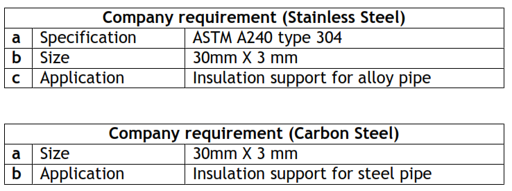
8. MATERIALS:
QC Inspector shall verify after the receiving of material if it is approved for the project and also the expiry of the product. The basic materials which will use by the Subcontractor for the execution of Insulation activities,
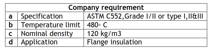
8.1 Hot Insulation Materials:
(i) Mineral fiber preformed pipe covering
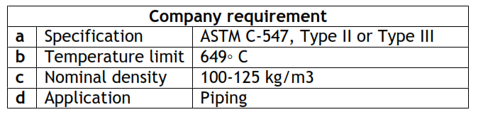
(ii) Mineral fiber Blanket
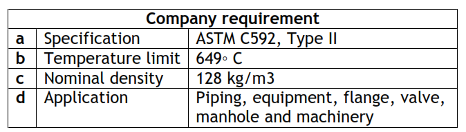
Note: For carbon steel the insulation shall have one side wire mesh stitched with galvanized wire. For stainless steel piping and equipment stainless steel wire mesh shall be stitched using stainless steel wire.
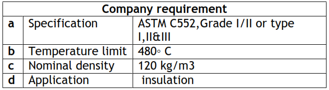
(iii) Cellular Glass (CG)
(iv) Aluminized Steel


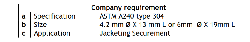
(v) Stainless steel Band & Seal

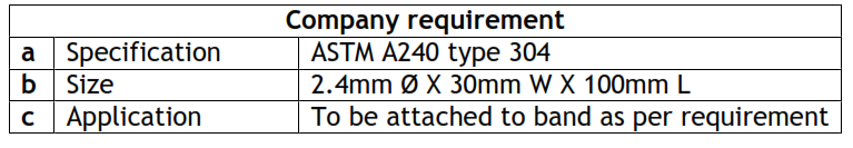
(vi) Stainless steel Wire
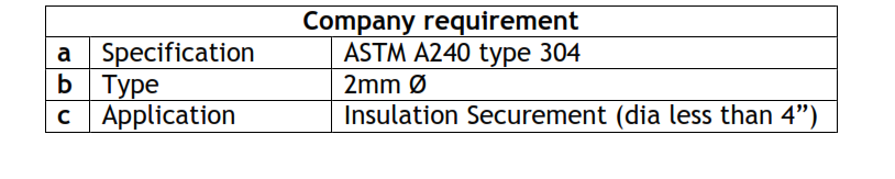
(vii) Stainless steel Self Tapping Screw with washer
(viii) Stainless steel Expansion Spring
(ix) Stainless steel Toggle Clip

8.2 Cold Insulation Materials:
(i) Cellular Glass (CG)
(ii) Vapor Barrier Mastic

Vapor barrier shall have a water vapor permeance as per ASTM E96. Fabric reinforcement of elastomeric coating is required.
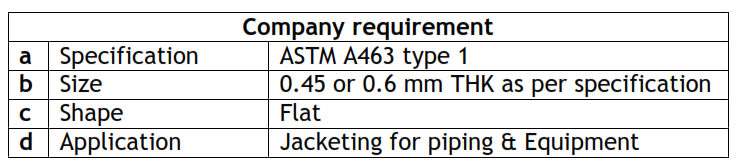
(iii) Aluminum Sheet

Note: For Piping with less than 6” dia will jacket with 0.5mm Flat.
Piping with less than 20” dia will jacket with 0.6mm Flat.
Piping with more than 20” dia will jacket with 0.8mm Flat.
(iv) Aluminized Steel Sheet
Note: Aluminized sheet is for Equipments & (Piping at fire Hazardous area). Piping in fire hazardous are with less than 36” dia and all equipment with less than 36” will jacket with 0.45mm Flat sheet.
All Equipments and (fire hazardous area piping) with more than 36” dia will jacket with 0.6mm flat.
(v) Stainless steel Band & Seal

(vi) Support Ring (SS or Carbon Steel Flat bar)
9. WORK FLOW CHART:
9.1 HOT INSULATION WORK SEQUENCE:
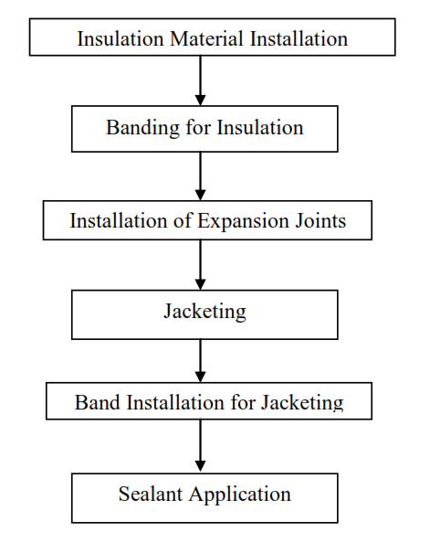
9.2 COLD INSULATION WORK SEQUENCE:

10. PRE APPLICATION PREPARATION:
(i) Handing over report from Equipment/Piping department shall be given at the time when the equipment/piping is released for insulation works.
(ii) Insulation shall not be applied until hydrostatic and other testing has been completed.
(iii) Painting release paper shall be attached to the RFI in order to start the insulation.
(iv) All surfaces to be insulated shall be clean and dry, insulation shall not be applied over wet surfaces.
(v) If any damages found immediately report to the contractor representative prior to start the insulation activities.
(vi) Authorization to proceed with application of insulation shall be obtained in writing from the Contractor.
(vii) Make sure that the materials delivered to site are comply with the specification and latest review drawings.
(viii) Latest revision of drawings must be issued for the proper control of work.
(ix) Surface preparation RFI shall be raised.
(x) The construction department shall wait for the final confirmation from QC department prior to start the work.
11. INSULATION PROCEDURE:
(i) All materials shall be stored, mixed, thinned and applied in accordance with the manufacturer’s printed instructions.
(ii) All conflicts between the method statement and manufacturer’s instructions shall be brought to the attention of Contractor for resolution.
(iii) Insulation shall not be applied over wet surfaces.
(iv) Insulation section shall be trimmed as required to achieve tight fit without voids.
(v) Fabricated or preformed insulation shall fit curvature of the surface to be insulated.
(vi) If applying single layer insulation other than hinged pipe covering the circumferential butt joints of each half section shall be staggered.
(vii) If applying multi layer insulation each layer shall be staggered to the longitudinal and circumferential joint of the layer beneath.
(viii) Each layer of insulation shall be held in place separately.
(ix) Insulation shall be applied as single layer for thickness less than 90mm.
(x) All insulation shall be free from cracks, voids and gaps. All cracks, voids etc greater than 3mm shall be refitted not filled.
(xi) Vessels and tanks shall be insulated with blanket insulation.
(xii) Installed insulation shall have the required permanent or temporary protection applied before the conclusion of days work.
(xiv) INSULATION MATERIALS SHALL BE HANDLED AND DISPOSED OF IN ACCORDANCE WITH APPLICABLE FEDERAL, STATE, AND LOCAL LAWS AND REGULATIONS.
11.1 Hot Insulation:
The Hot insulation installation will cover the following two major categories in this Project
Hot Insulation for Piping & Hot Insulation for Equipment
11.1.1 Hot Insulation Procedure for Piping:
The hot insulation of piping shall have mainly 6 activities which are stated in Section 9.1 of this Method Statement.
(i) All insulation materials shall be protected from rain and moisture.
(ii) Insulation sections shall be trimmed as required to achieve close fit to avoid major void and gaps.
(iii) All hot piping insulation shall be done with mineral fiber (blanket/section)
(iv) All piping insulation with single layer less than or equal to 8” shall be installed by preformed pipe section.
(v) Sectional insulation shall be sized to eliminate gaps and voids between surfaces and the insulation.
(vi) Sectional insulation shall be applied so all end joints are staggered.
(vii) Insulation shall be secured with SS wire or Bands spaced at max. 250mm.
(viii) For vertical piping insulation the support ring will install directly above all elbows, flanges or flanged valves. Additional support will install at every 6425mm of uninterrupted length.
(ix) Elbow 4” and over shall be insulate with mitered cut.
(x) Insulation shall be terminate at a distance of (bolt length+25mm) flanges and valves occur.
11.1.2 Hot Insulation Procedure for Equipment:
The hot insulation of piping shall have mainly 6 activities which are stated in Section 9.1 of this Method Statement.
(i) All insulation materials shall be protected from rain and moisture.
(ii) Equipment insulation support ring, pins, clips and accessories shall be compatible with equipment material.
(iii) All hot equipment insulation shall be done with mineral fiber blanket.
(iv) Insulation on both the inside and the outside of skirts shall be equal to the shell insulation thickness.
(v) Insulation shall be sized to eliminate gaps and voids between Surfaces and the insulation.
(vi) Insulation materials shall be secured with bands on every 250 mm maximum Centers.
(vii) For vertical equipment with skirts, insulation on bottom heads only shall be held in place by bands.
(viii) Insulation for instrument shall be applied in a way so that there is no interference with either the operation or function of instrument and allow all gauges.
(ix) Expansion joints shall not be applied on equipments having temperature up to 650◦ C.
(x) Insulation shall be terminate at a distance of (bolt length+25mm) flanges and valves occur.
11.2. Cold Insulation:
The Cold insulation installation will cover the following two major categories in this Method statement.
Cold Insulation for Piping &
Cold Insulation for Equipment
11.2.1 Cold Insulation Procedure for Piping:
The cold insulation of piping shall have mainly 8 activities which are stated in Section 9.2 of this Method Statement.
(i) All insulation materials shall be protected from rain and moisture.
(ii) The thickness greater than 76mm will be install by multi-layer insulation.
(iii) All cold piping insulation shall be done with cellular glass.
(iv) Insulation Up to 12” OD will secure by fiberglass reinforced tape.
(v) Insulation shall be sized to eliminate gaps and voids between Surfaces and the insulation.
(vi) Insulation Up to 36” OD from 12” will secure by 12mm band.
(vii) Insulation over 36” OD will secure by 20mm band.
(viii) Insulation securement shall be spaced on a maximum of 250mm.
(ix) Protrusion through insulation on piping will insulated for a minimum distance equal to 4 times of adjacent insulation thickness.
(x) Insulation thickness on protrusions shall be half of adjacent insulation thickness.
(xi) Insulation thickness on protrusions shall be 38 mm, if the half value of adjacent insulation comes less than 38mm.
(xii) Vapor stops that seal the insulation to pipe shall be installed at all insulation terminations.
(xiii) Vapor stop shall extend a minimum of 50mm from insulation termination point.
Vapor Barrier Installation.
(xiv) Before the application of jacketing all insulated surface shall be sealed with vapor barrier sheet.
(xv) Vapor barrier sheet shall be installed without gaps or folds with 50mm overlap.
11.2.2 Cold Insulation Procedure for Equipment:
The cold insulation of equipment shall have mainly 8 activities which are stated in Section 9.2 of this Method Statement.
(i) All insulation materials shall be protected from rain and moisture.
(ii) The thickness greater than 76mm will install by multi-layer.
(iii) All cold equipment insulation shall be done with cellular glass.
(iv) Insulation Up to 12” OD will secure by fiberglass reinforced tape.
(v) Insulation shall be sized to eliminate gaps and voids between Surfaces and the insulation.
(vi) Insulation Up to 36” OD from 12” will secure by 12mm band.
(vii) Insulation over 36” OD will secure by 20mm band.
(viii) Insulation securement shall be spaced on a maximum of 250mm.
(ix) Protrusion through insulation on equipment will insulated for a minimum distance equal to 4 times of adjacent insulation thickness.
(x) Insulation thickness on protrusions shall be half of adjacent insulation thickness.
(xi) Insulation thickness on protrusions shall be 38 mm, if the half value of adjacent insulation comes less than 38mm.
(xii) Vapor stops that seal the insulation to equipment shall be installed at all insulation terminations.
(xiii) Vapor stop shall extend a minimum of 50mm from insulation termination point.
Vapor Barrier Installation.
(xiii) Before the application of jacketing all insulated surface shall be sealed with vapor barrier sheet.
(xiv) Vapor barrier sheet shall be installed without gaps or folds with 50mm overlap.
11.3 Weatherproofing Installation (INSULATION JACKETING):
(i) All external surface of insulation shall have a weather barrier finish to keep Insulation dry and provide mechanical protection.
(ii) All joints shall be fabricated with proper overlap and to prevent moisture penetration.
(iii) All joints shall be caulked with silicone sealant to stop moisture entry.
(iv) Screws if used shall not penetrate the vapor barrier in cold insulation.
11.3.1 Jacketing Procedure for Piping:
(i) Jacketing for horizontal and vertical cylindrical piping shall have minimum 50mm circumferential and longitudinal laps
(ii) The longitudinal lap on horizontal piping shall be between four o’clock and eight o’clock position to shed rain water.
(iii) On vertical piping, the upper course of jacketing shall overlap the lower.
(iv) On vertical pipes, upper course shall be supported by “S” clips.
(v) Jacketing shall be secured with stainless steel bands on appox. 300 mm centers.
(vi) Smooth sheet of 0.4~0.6 mm shall be used for boxes.
(vii) Two pieces elbow shall be installed up to 3”.
(vi) The jacketing shall be secured with self-tapping screws.
11.3.2 Jacketing Procedure for Equipment:
(i) Jacketing shall be applied with 50mm overlap on all seams.
(ii) On vertical vessels, provide a minimum of two corrugations overlap.
(iii) On vertical vessels, the upper course of jacketing shall be supported by S-clips, on max. 450mm centers.
(iv) Jacketing shall be secured with bands on 450mm centers and one in each Circumferential lap (Preventing sliding “U” clip shall be applied on max.1220mm distance).
(v) Jacketing shall be secured with stainless steel bands on approx. 300 mm centers.
(vi) Smooth sheet of 0.4~0.6 mm shall be used for boxes.
(vii) Sheet metal screws shall be installed on longitudinal joints at 150mm centers (not required in circumferential laps).
(vi) The jacketing shall be secured with self-tapping screws.
12. TML PLUG INSTALLATION:
(i) The use of inspection plugs is applicable only for hot insulated surface of Piping/Equipment
(ii) Removable insulation plug shall be provided to permit on-stream ultrasonic inspection when required by the operating proponent.
(iii) The inspection plugs shall be vapor tight.
(iv) The material for removable insulation plug shall be NDT Inspection Plug(Aluminum/EPDM) OR equivalent.
(v) All hot piping insulation up to 6” shall be installed by 1.5” inspection plug.
(vi) All hot piping insulation 6” and more shall be installed by 2.5” inspection plug.
(vii) All hot equipment insulation shall be installed by 5” inspection plug.
(viii) Removable insulation plug shall be provided to permit on-stream ultrasonic inspection when required by the operating proponent.
(ix) Subcontractor will make the inspection window only after finishing the markings of contractor representative.
13. DRESS UP INSULATION WORK:
(i) Prior to the actual dress-up insulation work schedule, insulation subcontract should prepare and deliver on site all required insulation materials including ancillaries and sealants.
(ii) Properly store all said materials on a pallet near the equipment(s) and cover with tarpaulins. If required, secure using tie-wires on nylon rope.
14. REPAIR WORK PROCEDURE:
(i) Damage to insulation weather jacketing shall be repaired immediately if the damage can result in additional damage to the insulation due to water leakage into the system.
(ii) If permanent repair is not immediately practical, temporary repair of damaged weather jacketing shall be required.
(iii) Damaged insulation shall be replaced if the nature of the will adversely affect the thermal performance of the system
15. QUALITY CONTROL:
(i) Application of insulation inspection shall be based in accordance with SATIP-N-001-01/02
(ii) All equipment shall have Work Transfer Sheet and turned-over by respective department prior to insulation.
(iii) During acceptance testing by the Contractor or Owner a check shall be run by the insulation subcontractor to ensure that all inspections have been carried out and the results are satisfactory.
(iv) Items that are not in accordance with the purchase order shall be subjected to rejection.
(v) All materials, fabrication, and installation work is subjected to inspection by the Contractor or the Owner.
(vi) Bands used to secure the insulation shall be installed straight and in proper tension.
(vii) Stages of inspection and verification, characteristics to be checked, acceptance criteria and inspection / verification authority for hot insulation shall be as per Inspection and Test Plan
(viii) Inspection and test records of insulation shall be as per Quality Control Report.
(ix) All Inspection requirements to be comply as per SATIP-N-001-01/02.
16. HEALTH, SAFETY ENVIRONMENT:
Approved work permit shall be obtained prior to the start any insulation works.
All personnel should undergo Safety induction before starting the job.
The insulation crew must carry out a safety risk assessment prior to start of any activities.
The necessary manpower inclusive of supervisory staff, tools, equipment, material and other resources required must be made available and ready for use.
Workers shall wear Personal Protective equipment’s (PPE’s) required for the work. Certified permit receiver, firewatcher and work in-charge should be at work site during
the execution of the work.
Full body harness shall be worn at all times when working at elevated platform above 1.8meters.
Tools to be secured with tag line during use to prevent possibility of injury due to falling objects.
A ½ inch diameter wire rope must be provided for safety lifeline.
Good housekeeping shall be maintained in the duration of works.
Material Safety Data Sheets for each product will be available always in the site office Job Safety Analysis for the work should be prepared and awareness should be given to the workers about safe procedures.
Proper washing facilities should be provided for emergency situations.