1. Common Clock.
Common clock enables all Radio Access Technologies (RATs) in a multimode base station to share a single clock source. This reduces both capital expenditure (CAPEX) and operating expenses (OPEX) by eliminating the need for separate clock equipment for each RAT. The use of a common clock is especially beneficial for co-sited multimode base stations, simplifying the infrastructure and enhancing cost-efficiency.
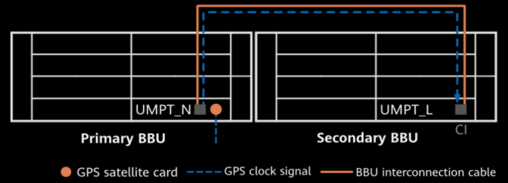
Common clock in multimode base stations supports scenarios like separate-MPT, where each RAT can either use its own external clock source or share the clock source from another RAT. This setup reduces configuration conflicts and simplifies infrastructure. In multimode base stations, RATs can share a clock through the BBU backplane if located in the same BBU or through BBU interconnection when configured in separate BBUs. This approach optimizes clock resource utilization and minimizes costs.
The following are the restrictions on using common clock in separate-MPT scenarios:
In separate-MPT scenarios, common clock usage is restricted based on the synchronization configuration of the RAT providing the clock source. For example, if frequency synchronization is used by the source RAT, only frequency synchronization can be used by the other RATs. If time synchronization is used, loose time synchronization may be applied. Additionally, if hybrid synchronization is used by the source, only frequency synchronization can be shared. Low-precision frame synchronization also restricts the shared RATs to frequency synchronization.
Co-MPT scenarios: The clock source configured on the main control board is shared between each RAT and common clock must be used by default, as shown in figure 3.


2. Clock Lock in CPRI SDR Scenarios.
In separate-MPT multimode SDR scenarios, the RF clock is synchronized with the baseband clock of only one RAT. This synchronization creates a deviation from the clocks of other RATs. To counter this, a FIFO mechanism is employed. However, for the system to function correctly, the clocks of all RATs must remain strictly synchronized. If synchronization is not maintained, FIFO overflow can occur, leading to data slips.
A slip occurs when the clock deviation between two devices exceeds a threshold, causing data to be either lost or inserted. For instance, if the write clock is faster than the read clock, the memory buffer fills up and discards unread data. Conversely, if the write clock is slower, dummy read operations lead to pseudo-data being inserted, resulting in signal distortion. Proper clock synchronization between devices prevents these issues.
Principles.
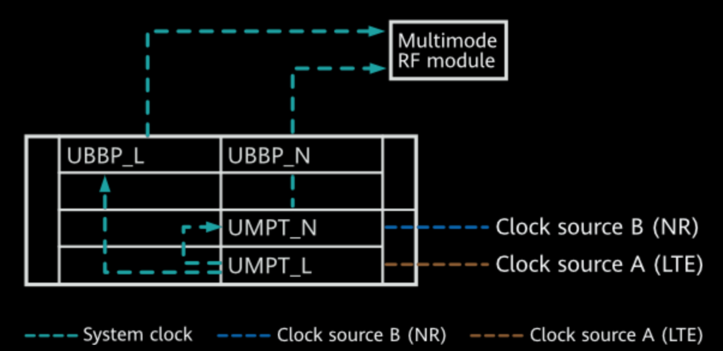
The clock lock function ensures that all RATs in a multimode base station use a synchronized clock provided by the main control board of a designated “major standard” RAT. This minimizes clock signal deviation, as the major standard generates the system clock and shares it with the other RATs. For example, in an LTE/NR SDR scenario, LTE serves as the major standard, providing its system clock to the NR baseband unit, which then passes it to the RF module, ensuring precise synchronization between both RATs.

System Clock Lock Optimization.
System clock lock optimization allows a multimode base station to automatically select the RAT with the best clock quality as the major standard, ensuring optimal clock performance. This feature addresses limitations in systems where GSM must be the major standard due to the GTMU’s constraints, improving overall clock synchronization quality across the base station.
System Clock Lock Issues.
System clock lock causes clock coupling between RATs, which leads to potential issues such as a reduction in synchronization precision and clock holdover capability for NR when paired with LTE as the major standard. Additionally, the upgrade, reset, startup, or fault of one RAT in a multimode base station can impact the operation of other RATs, creating a dependency that can affect overall performance.
3. Clock Unlock in eCPRI SDR Scenarios.
The rapid evolution of wireless communications has increased the need for high transmission bandwidth between the baseband unit (BU) and remote unit (RU). CPRI (Common Public Radio Interface) bandwidth is limited, so eCPRI (enhanced CPRI) was introduced. eCPRI replaces time-division multiplexing (TDM) with Ethernet transmission, improving transmission efficiency and bandwidth usage. By utilizing Ethernet ports with large receive buffers, eCPRI prevents slips, unlike CPRI, which has lower transmission efficiency and higher bandwidth requirements.
Principles.
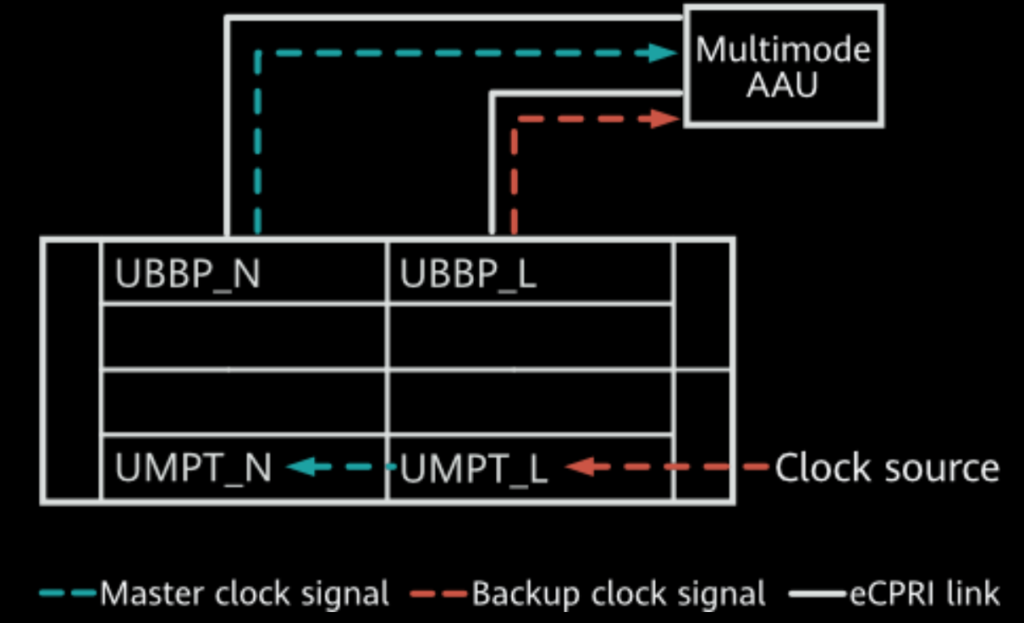
Clock unlock in eCPRI scenarios resolves clock lock issues by decoupling the clocks of different RATs. Each RAT maintains its own system clock, with one RAT’s clock serving as the master and another as the backup. If the master clock fails, the multimode AAU switches to the backup clock. This function ensures synchronization between different RATs and limits delay deviation. It requires the SRAN17.0 or later software version for base stations.

Prerequisites for this article are: