When performing insulation resistance tests using a Megger insulation tester, it’s crucial to understand how to connect the instrument to various types of electrical equipment. Proper connections ensure accurate test results and safety. Here are diagrams and explanations for connecting a Megger to different equipment:
1. AC Motors & Starting Equipment:
- Connections are made for testing the insulation resistance of an AC motor, its starting equipment, and connecting lines in parallel.
- Note that the starter switch should be in the “on” position during the test.
- It’s generally preferable to disconnect component parts and test them separately to identify weaknesses.

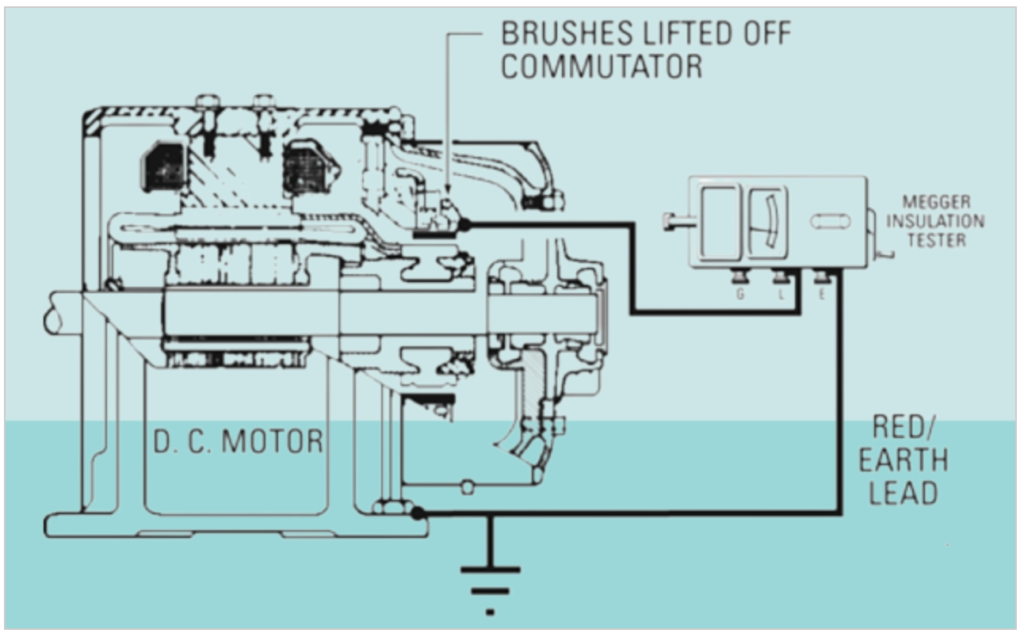
2. DC Generators & Motors:
- By raising the brushes as indicated, you can test the brush rigging and field coils separately from the armature.
- Lowering the brushes allows testing of the brush rigging, field coils, and armature combined.
3. Wiring Installation:
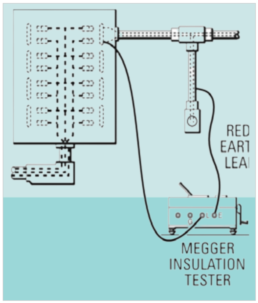
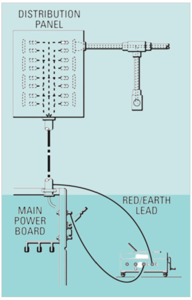
- Connections for testing individual circuits to ground, starting from the distribution panel.
- At the main power board, you can test the entire system to ground simultaneously if all switches in the distribution panel are closed.
4. Appliances, Meters, Instruments & Miscellaneous Electrical Apparatus:
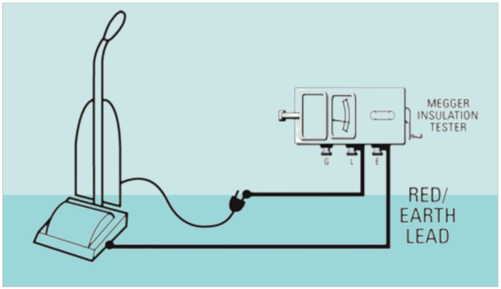
- Connections for testing an appliance’s insulation resistance. The test is conducted between the conductor (e.g., heating unit or motor) and exposed metal parts.
- The apparatus must be disconnected from any power source and placed on insulating material.
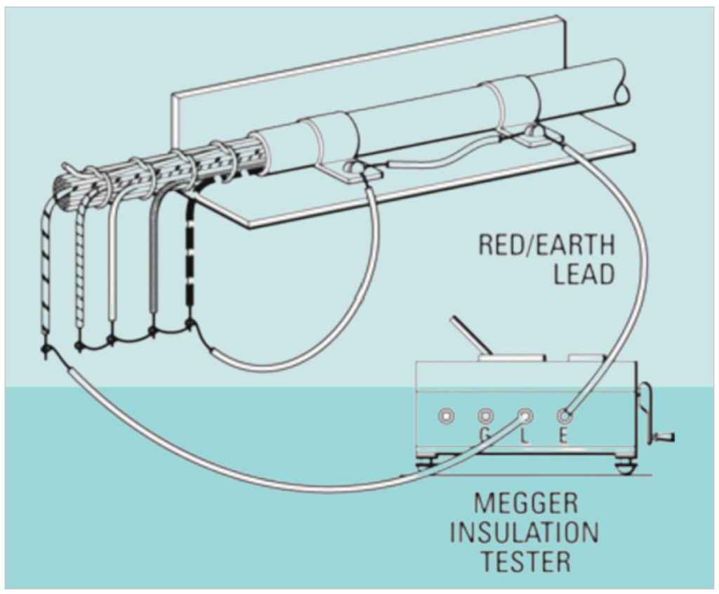
5. Control, Signaling & Communication Cables:
- Connections for testing the insulation resistance of one wire within a multiconductor cable against all other wires and the sheath connected together.
6. Power Cables:
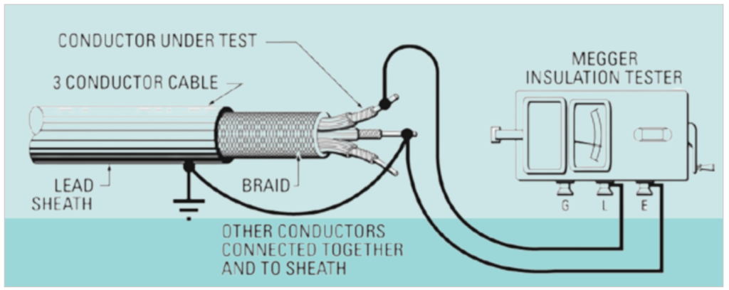
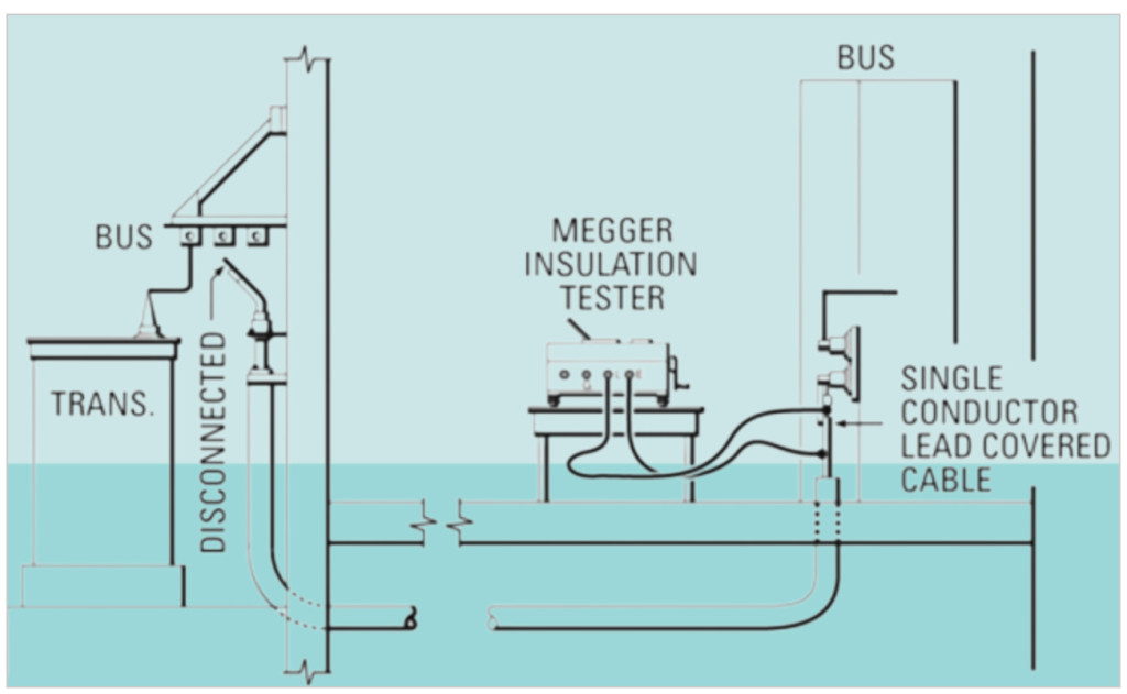
- Connections for testing the insulation resistance of a power cable.
- When testing a cable, it’s usually best to disconnect it at both ends to test the cable separately and avoid errors due to leakage across or through switchboards or panelboards.
7. Power Transformers:
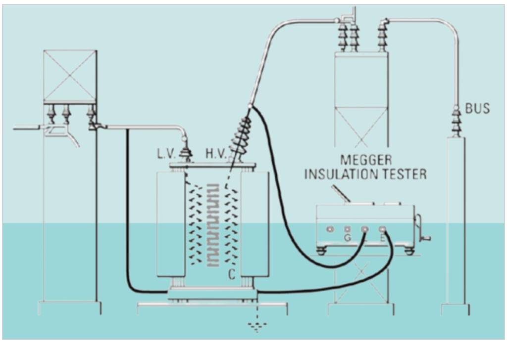
- Connections for testing the insulation resistance of a power transformer’s high voltage winding and bushings, along with the high-tension disconnect switch, in parallel.
- The low voltage winding should be grounded for this test.
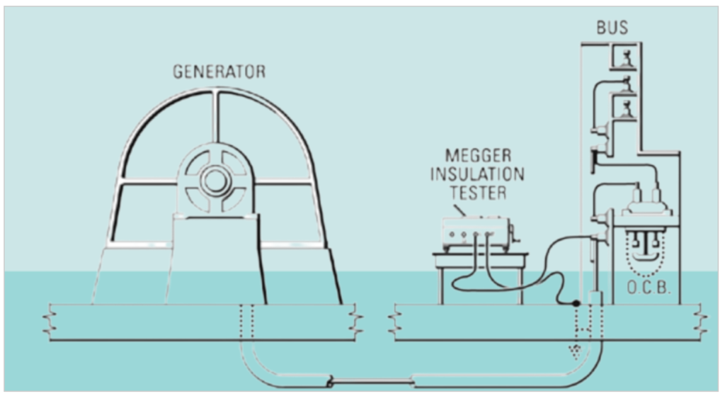
8. AC Generators:
- With this connection, the insulation resistance is determined by the generator stator winding and connecting cable combined.
- To test either the stator winding or the cable separately, the cable must be disconnected from the generator.
Remember, the Megger insulation tester measures the resistance between its terminals, which may include resistance within insulation or along its surface. Proper connections are essential for accurate results. Prioritize safety and follow the manufacturer’s guidelines when conducting insulation resistance tests on electrical equipment.
Related Articles:
What is Good insulation?
What Makes Insulation Go Bad?
How Insulation Resistance is Measured.
How to Interpret Resistance Readings.
Factors Affecting Insulation Resistance Readings.
Types of Insulation Resistance Tests.
Test Voltage vs. Equipment Rating.
AC Testing vs. DC.
Use of DC Dielectric Test Set.
Tests During Drying out of Equipment.
Effect of Temperature on insulation Resistance.
Effects of humidity.
Preparation of Apparatus to test.
Safety Precautions.
Additional Notes About using A Megger Insulation Tester.
Interpretation-Minimum Values.
Minimum Values for Insulation Resistance.
Tests Using Multi-Voltage Megger Insulation Testers.
Step-Voltage Method.
Use of a Guard Terminal.
Outdoor Oil Circuit Breaker.