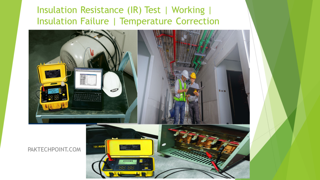
What is Insulation Resistance Test?
Insulation resistance, as defined by IEEE 43, refers to the ability of the electrical insulation within a winding, such as that in a motor or transformer, to resist the flow of direct current (DC). In simpler terms, it measures how effectively the insulation material can prevent the leakage or loss of electric current through it when a DC voltage is applied.
Insulation resistance is a crucial parameter in electrical systems because it indicates the health and integrity of the insulation material. High insulation resistance means that the insulation is effectively blocking the flow of DC current, which is desirable because it helps prevent electrical leakage and ensures the safe operation of the equipment. On the other hand, low insulation resistance indicates that the insulation may be compromised, possibly due to moisture, contaminants, or physical damage, and this can lead to electrical faults, short circuits, or breakdowns.
Insulation resistance testing is a common maintenance and diagnostic procedure performed on electrical equipment to assess its condition. By measuring the insulation resistance, technicians can detect potential issues early, allowing for preventive maintenance and avoiding costly failures or accidents.
Insulation Resistance Test How it Works?
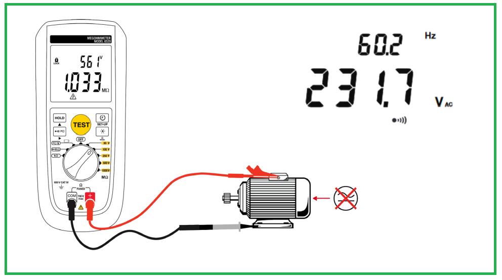
An insulation resistance tester, also known as a Megohmmeter, is a specialized instrument used to assess the quality of insulation in electrical devices or systems. It operates by applying a known voltage to the device being tested, measuring the resulting leakage current, and then calculating the insulation resistance based on Ohm’s Law (Resistance = Voltage / Current).
Here’s how it works in more detail:
- Known Voltage Application: The tester generates a known and controlled voltage, typically a direct current (DC), and applies it to the device or system under examination.
- Leakage Current Measurement: While the voltage is applied, the tester measures the current that flows through the insulation material. In a well-insulated system, this current should be minimal, indicating high resistance to electrical leakage.
- Calculation of Insulation Resistance: Using Ohm’s Law (R = V/I), where R is resistance, V is voltage, and I is current, the tester calculates the insulation resistance. This resistance value is typically expressed in Megaohms (MΩ) or Ohms (Ω), depending on the scale of the measurement.
- Interpretation: The measured insulation resistance is compared to predetermined standards or acceptable thresholds. Lower insulation resistance values may indicate compromised or deteriorating insulation, while higher values suggest good insulation quality.
- Safety: It is essential to ensure that the device under test is de-energized during the testing process to prevent electrical hazards. This means that the equipment should be disconnected from its power source before conducting insulation resistance testing.
Why we need Insulation Resistance Test?
Insulation resistance testing is a critical part of routine maintenance, commissioning, and troubleshooting activities in electrical systems. It helps identify potential issues with insulation, such as moisture ingress, contamination, or damage, which can lead to electrical faults or breakdowns if left unaddressed. Regular testing and monitoring of insulation resistance are essential for ensuring the safety and reliability of electrical equipment and systems.
Preventive and diagnostic maintenance in electrical systems are essential practices to ensure the safety, reliability, and optimal performance of electrical equipment and installations. Safety is a primary concern in both preventive and diagnostic maintenance, with the overarching goals of minimizing electric shock hazards and reducing the risk of electrically induced fire hazards.
Preventive and diagnostic maintenance play a crucial role in managing costs associated with electrical equipment and systems. These maintenance practices help address cost-related factors, such as minimizing downtime, reducing repair or replacement expenses, and optimizing overall operational efficiency.
Insulation resistance testing with a Megohmmeter helps installers and contractors in several ways:
- Early Detection of Insulation Issues: It finds defects in insulation during wire installations, saving time and avoiding costly return visits.
- Locating Shorts and Breaks: In new construction, it identifies wiring shorts and breaks before walls are closed, preventing invasive fixes later.
- Ensuring Electrical Safety: It verifies that electrical systems are safe by detecting insulation problems that could pose risks.
- Quality Assurance: It ensures the reliability and performance of electrical installations, leading to customer satisfaction.
- Documentation and Compliance: Test results serve as proof of quality work and compliance with standards, reducing disputes and ensuring legal requirements are met.
How Often Should You Test:
The frequency of insulation resistance testing depends on the equipment and its operating conditions:
- Annually: For less critical equipment in clean environments with intermittent use.
- Every 3 to 6 Months: For critical equipment like motors and pumps that operate continuously in harsh conditions (hot, dusty, oily) and are exposed to constant vibration.
Regular testing helps identify issues early, reducing the risk of failures and ensuring the safety and reliability of electrical systems.
Reasons For Motor Failure:
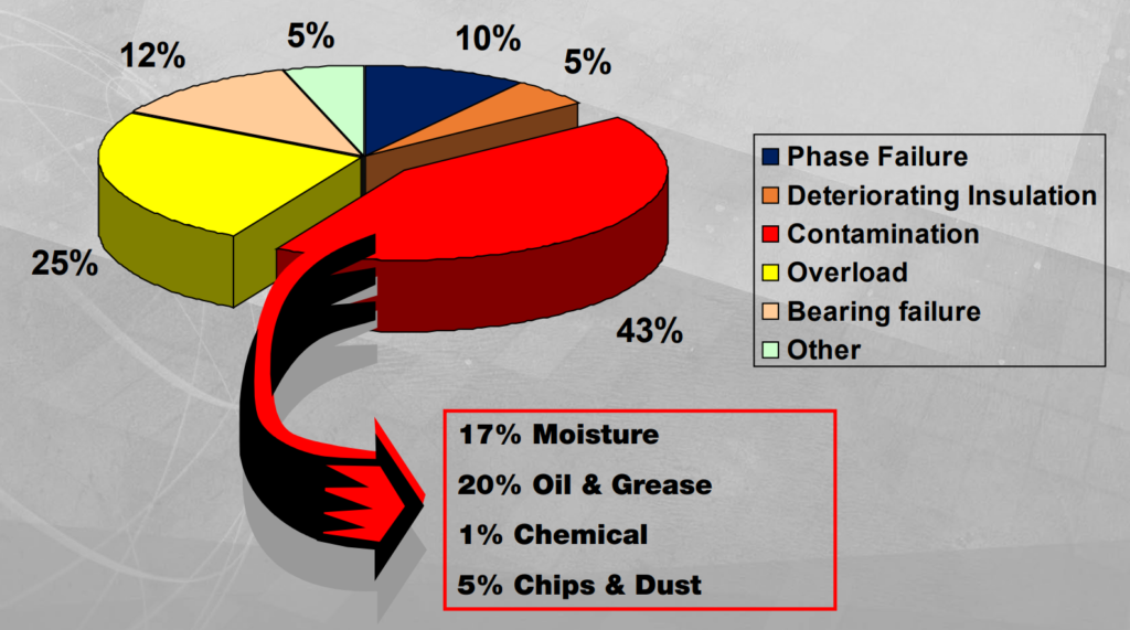
What Causes Insulation Failure:
Insulation failure in electrical systems can be attributed to five main factors:
- Electrical Stress: High voltage or electrical surges can weaken and break down insulation over time.
- Mechanical Stress: Physical damage, vibration, or mechanical strain can compromise insulation integrity.
- Chemical Stress: Exposure to corrosive chemicals or substances can degrade insulation materials.
- Thermal Stress: Extreme temperatures, both high and low, can cause insulation to deteriorate.
- Environmental Contamination: Dust, moisture, and other environmental factors can penetrate and damage insulation.
Understanding these initiators is crucial for preventing insulation failure and ensuring the safety and reliability of electrical systems.
Principle of Measurement
The principle of measuring insulation resistance involves these steps:
- Inject a Known Voltage: Apply a known voltage, typically in kilovolts (Kv), to the insulation being tested.
- Measure the Leakage Current: Measure the leakage current that flows through the insulation at the applied voltage. This current represents any electrical leakage or conductivity in the insulation.
- Calculate Insulation Resistance: Calculate the insulation resistance (usually in megohms) using Ohm’s law: R (Megohms) = V (Kv) / I (mA), where R is the insulation resistance, V is the applied voltage, and I is the measured leakage current in milliamperes (mA).
This measurement helps assess the quality of electrical insulation in a device or system, with higher insulation resistance values indicating better insulation quality and lower risk of electrical leakage or breakdown.
The principle of measurement for Hipot (High Potential) testing and Megohmmeter testing can be differentiated as follows:
- Hipot Testing: This test primarily focuses on identifying issues like gaps or clearances between conductive parts and the ground, pinholes in insulation, and other forms of degradation. Hipot testing may sometimes cause damage to the insulation being tested, and it’s more about detecting potential weaknesses rather than providing a precise quantitative measurement.
- Megohmmeter Testing: Megohmmeter, also known as Insulation Resistance testing, aims to provide an actual quantitative measurement of the insulation quality. It is a nondestructive test that calculates the insulation resistance in ohms, indicating how effectively the insulation resists the flow of current. Megohmmeter testing is more precise and focuses on evaluating the actual insulation condition.
In summary, while both tests deal with insulation, Hipot testing is more about identifying potential issues, while Megohmmeter testing provides a quantitative assessment of insulation quality without causing damage.
Understanding The Numbers:
These conversions help you understand the scale of resistance measurements:
- Megohm (MΩ): 1 Megohm is equal to 1,000,000 ohms (1×10^6 Ω).
- Gigohm (GΩ): 1 Gigohm is equal to 1,000,000,000 ohms (1×10^9 Ω).
- Teraohm (TΩ): 1 Teraohm is equal to 1,000,000,000,000 ohms (1×10^12 Ω).
These units are used to represent extremely high resistance values in electrical measurements, especially in insulation resistance testing where the resistance values can be very large due to the nature of insulating materials.
Conducting Insulation Resistance Tests
To conduct insulation resistance testing, you will need the following equipment:
- Megohmmeter with Timed Test Function: This instrument is the primary tool for measuring insulation resistance. It applies a known voltage to the insulation and measures the resulting leakage current. The timed test function allows you to record readings over a specific period to assess the stability of insulation resistance.
- Temperature Indicator: Monitoring the temperature of the equipment or the environment is crucial because insulation resistance values can be temperature-dependent. Some megohmmeters have built-in temperature compensation features, but having a separate temperature indicator provides additional accuracy.
- Humidity Meter: A humidity meter is necessary if the equipment or testing environment is close to or below the dew point. Low humidity can affect insulation resistance readings. If the humidity level is below the dew point, moisture condensation may occur, impacting the accuracy of the test. Monitoring humidity ensures that the testing conditions remain consistent.
These tools help ensure accurate and reliable insulation resistance measurements, especially when testing critical electrical equipment or in environments with varying conditions.
Safety during IR Test
Here are some safety considerations and requirements for performing insulation resistance testing:
- Testing on De-energized Equipment: It’s essential to emphasize that insulation resistance testing should only be conducted on equipment that is completely de-energized. This ensures the safety of the personnel performing the test and prevents damage to the testing equipment. Always follow proper lockout/tagout procedures when working with electrical systems.
- Voltmeter Function: While the primary function of the megohmmeter is to measure insulation resistance, it’s beneficial to have a voltmeter function as well. This allows you to verify the voltage applied to the insulation during the test, ensuring that it matches the selected test voltage. It also helps in identifying any issues with the test voltage source.
- Capacitance Circuits Requiring Discharging: In some cases, the equipment being tested may have capacitance circuits. Before conducting the insulation resistance test, it’s crucial to discharge these capacitance circuits to ensure accurate readings. Failure to discharge capacitors can lead to false readings and potential safety hazards. Follow proper discharge procedures for any capacitors in the system.
Test Currents in Insulation
When conducting insulation resistance testing, it’s important to understand that the total current in the body of the insulation is comprised of three main components:
- Capacitance Charging Current: This component of current arises due to the charging and discharging of the capacitance within the insulation material. When a voltage is applied to the insulation during testing, it takes some time for the insulation’s capacitance to charge fully. As a result, there is an initial surge of current, known as the capacitance charging current. Once the capacitance is charged, this current component decreases significantly.
- Absorption Current: Absorption current, also referred to as polarization current, is a component that arises due to the gradual polarization of the insulation material over time. When voltage is applied, the insulation may absorb some of this energy, and this absorbed energy is gradually released as a current. Absorption current tends to decrease over time as the insulation stabilizes.
- Leakage or Conduction Current: This is the component of current that represents any leakage or conduction of electricity through the insulation. In an ideal situation, insulation should not allow any current to pass through it. However, in real-world scenarios, there may be some degree of leakage or conduction due to imperfections or degradation of the insulation material. This component is of particular concern because it indicates potential insulation weaknesses.
Total current in the body of the insulation is the sum of three components
• Capacitance Charging Current • Absorption Current • Leakage or Conduction Current
Insulation Resistance Readings
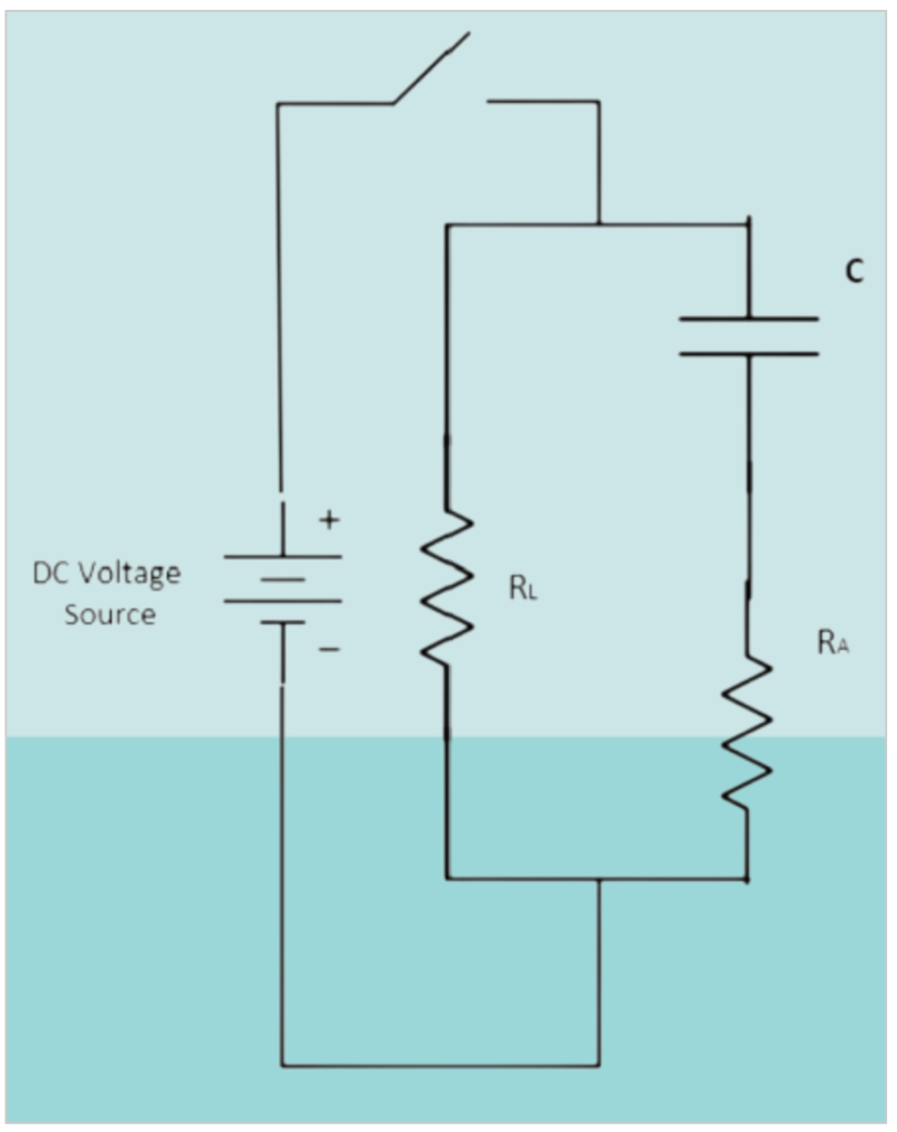
Insulation resistance readings obtained during testing are indeed time-dependent, and they provide valuable insights into the condition of the insulation material. Here’s how the readings change over time during an insulation resistance test:
- Capacitance Current (C): When the test voltage is initially applied, the insulation exhibits a high capacitance charging current. This current is primarily associated with the charging of the insulation’s capacitance. It appears as a rapid increase in the reading when the voltage is first applied. However, this current quickly stabilizes within the first few seconds of the test.
- Absorption Current (RA): After the initial surge of capacitance current, the absorption current becomes more prominent. Absorption current represents the gradual polarization or absorption of energy by the insulation material. It typically starts to increase noticeably at around one minute into the test. This current component may continue to increase slowly over time, depending on the condition of the insulation material.
- Leakage Current (RL): As the test progresses, especially after about ten minutes or longer, the insulation resistance reading primarily reflects the leakage current. Leakage current is associated with any defects, impurities, or moisture present in the insulation. A high leakage current reading indicates that current is flowing through the insulation due to these issues. Monitoring this component is crucial for assessing the integrity of the insulation.
To observe these changing readings, digital instruments equipped with analog bargraph displays or analog instruments with needle movement are preferred. These visual representations allow the operator to track the behavior of the insulation over time and identify any abnormal trends or fluctuations in the readings. Such observations can provide valuable information about the condition of the insulation and whether further investigation or maintenance is required.

Temperature Correction in IR Test:
Rule of Thumb: For every 10-degree Celsius (or 18-degree Fahrenheit) increase in temperature, the insulation current approximately doubles, and the insulation resistance effectively halves.
In other words, as the temperature of the insulation material increases, its electrical resistance decreases. This is because higher temperatures can lead to increased molecular activity within the insulation material, which, in turn, can result in higher levels of leakage current in the insulation.

Test Methods:
Related Articles:
What is Good insulation?
What Makes Insulation Go Bad?
How Insulation Resistance is Measured.
How to Interpret Resistance Readings.
Factors Affecting Insulation Resistance Readings.
Types of Insulation Resistance Tests.
Test Voltage vs. Equipment Rating.
AC Testing vs. DC.
Use of DC Dielectric Test Set.
Tests During Drying out of Equipment.
Effect of Temperature on insulation Resistance.
Effects of humidity.
Preparation of Apparatus to test.
Safety Precautions.
Connections for testing insulation resistance of electrical equipment.
Additional Notes About using A Megger Insulation Tester.
Interpretation-Minimum Values.
Minimum Values for Insulation Resistance.
Tests Using Multi-Voltage Megger Insulation Testers.
Step-Voltage Method.
Use of a Guard Terminal.
Outdoor Oil Circuit Breaker.