Section | Title | Page | |
|
| |||
| Purpose | 2 | ||
| Scope | 2 | ||
| Related Documents | 2 | ||
| Cable Reels – Receipt and Testing | 2 | ||
| installation Procedures | 3 | ||
| Terminal Lugs | 3 | ||
| Taping of Lugs | 4 | ||
| Cable Splicing | 4 | ||
| Inspection and Testing | 4 | ||
| Change Log | 7 | ||
| Insulation Resistance Test Results | 8 | ||
| Overpotential Test Results for 5 kV Power Cable | 9 | ||
| Overpotential Test Results for 8 kV Power Cable | 10 | ||
| Overpotential Test Results for 15 kV Power Cable | 11 | ||
| Medium Voltage Cable Hi-Pot Test Lead Connection Details | 12 | ||
| Methods of Reducing Corona at Medium Voltage Cable Ends for Testing | 12 | ||
This technical specification outlines the essential requirements for the proper handling, installation, and testing of medium voltage cable systems. Medium voltage cables are a crucial component of electrical distribution systems and must be installed and maintained with precision to ensure safe and reliable operation. This document serves as a comprehensive guide to ensure compliance with industry standards and best practices when working with medium voltage cables.
International Codes and Standards Used for this Article:
Institute of Electrical and Electronic Engineers (IEEE)
IEEE 400 – Guide for Field Testing and Evaluation of the Insulation of Shielded Power Cable Systems Rated 5kV and Above.
National Fire Protection Association (NFPA)
NFPA 70 – National Electrical Code (NEC) – Latest Edition
NETA – International Electrical Testing Association
ATS-2013 Standard for ACCEPTANCE TESTING SPECIFICATIONS for Electrical Power Equipment and Systems.
Related Articles:
Electrical Work Method Statement for Plants and Refinery
4AEL-620304 Electrical Underground Work
4WCE-600001 General Scope of Work for Construction Contracts
STD-P312A Cable Grounding Connections Prysmian Airguard™ Cable
STD-P313A Cable Connections for Zero Sequence Relaying
- CABLE REELS – RECEIPT AND TESTING
4.1 The contractor shall provide Air Products with written acceptance of all furnished cable reels. This acceptance shall state that before installation the cable reel and visible portions of the cable(s) were visually checked and the cable reel and cable insulation or jacket appeared sound and undamaged. Any visible damage identified shall immediately be brought to the attention of an Air Products field representative.
4.2 All medium-voltage shielded cable shall be tested upon receipt on the cable reel. First perform dc insulation resistance test, then perform dc hi-pot test. Cable reels will be provided with sufficient exposed cable to perform these tests. Refer to Section 7 for complete cable testing and documentation procedures.
4.3 After testing is completed the conductor or cable ends shall be made weather proof using heat shrink cable end caps 3M or equal.
4.4 Cable reels shall be handled according to manufacturer’s instructions. All cable pulls shall be made directly from the reel.
Installation Procedures for Medium Voltage Cable
This section outlines the key installation procedures for medium voltage cable systems, emphasizing safety and compliance with industry standards and regulations. Proper installation is essential to ensure the reliability and performance of medium voltage cable systems.
5.1 General Requirements: Refer to specification [Electrical Work Method Statement] for comprehensive guidelines on electrical installations of cable in conduit and/or cable tray. Specification 4AEL-620302 provides information on medium voltage (MV) cable/wire types, and specification 4AEL-620304 covers direct-buried cable requirements.
5.1.1 Flexible Metal Conduit: When using flexible metal conduit for medium voltage equipment (above 600 volts), it must be approved for the voltage level of the conductors being installed. Flexible metal conduit may be used to connect to motor terminal enclosures over 600V in accordance with NEC Article 430, part XI.
5.2 Weather Tight Ends: If the cable is not enclosed within an electrical enclosure after installation, the ends must be made weather tight. This is achieved using heat shrink cable end caps from reputable brands like 3M or equivalent. Using bags or tape is not an acceptable method for protecting cable ends.
5.3 Termination Kits: Air Products typically provides termination kits for medium voltage cable termination. However, when Air Products does not supply the required items, the contractor must provide lugs (as per paragraph 6.1) and termination kits. Recommended termination kits include 3M Type Quick Term III or Raychem TFT-R series cold shrink cable terminations.
5.3.1 Proper Termination: The termination of medium voltage cables must adhere to the manufacturer’s recommendations for the specified cable and termination kits. Only materials recommended and provided by the cable manufacturer or Air Products should be used. To connect the shields of shielded cable and the ground stud of potheads or the grounding system, a minimum #6 AWG 600-volt insulated wire must be used.
5.3.2 Shield Grounding: Medium voltage power cable shields should be grounded at one location only, following standard STD-P313A, typically at the feeder breaker, starter, or switchgear end of the cable, unless specified differently on the contract drawings. Shields at the floating end should be securely tapped and insulated. Shields on Prysmian Airguard™ cable should be grounded at both ends per standard STD-P312A.
5.3.3 Heat Shrink: In cases where three conductor medium voltage power cable is used, the exposed portion of the individual conductor shield between the cable terminator and the termination kit should be covered with 1000V heat shrink for added safety and insulation.
Adhering to these installation procedures ensures the proper functioning and safety of medium voltage cable systems, reducing the risk of accidents and equipment damage. Compliance with manufacturer recommendations and industry standards is paramount throughout the installation process.
6. TERMINAL LUGS
6.1 Air Products normally provides the lugs necessary for terminating all cables and MV motor leads. Terminal lugs shall be 2-hole, electro-tin plated copper, seamless long barrel crimp type. Lug bolt hole size and spacing requirements shall be determined by the equipment buss plate design. Current approved manufacturers are Ilsco CLND series or (Hubbell) Anderson VHCL series. (No substitutions.)
6.1.1 Lugs shall be crimped using a dieless hydraulic compression tool of one of the following approved manufacturers. (No substitutions.)
Ilsco, Cat. No. IDT-6, manual tool
Ilsco, Cat. No. IDTB-6, battery powered
Square D Versa-Crimp, Cat. No. VC-7 or VC7-FT, manual tool
6.1.2 Air Products will provide the appropriate hydraulic compression tool on contractor request to the Air Products field representative. Contractor shall provide sufficient advanced notice to allow for scheduling and shipping of the tool. Contractor will be responsible for costs associated with repairs for any damage to tool while in their possession.
6.1.3 Three crimps are required on lugs for #2 AWG and smaller wire, six crimps are required on lugs for 350 kcmil and larger, and four crimps are required on lugs for intermediate sizes. Contractor shall rotate tool slightly during crimping so indents do not line up along lug barrel.
6.1.4 The contractor shall perform a “go/no-go” test using test slugs both before and after crimping each group of lugs of the same size. The test slug elongation is checked with a “go/no-go” test gauge. Alternately, test slug elongation can be measured with a caliper. Acceptable elongation dimension after compression shall be 19.812 to 20.574 mm (0.780 to 0.810 in). The test slugs shall be tagged and turned over to the Air Products field representative. Air Products will provide test slugs and gauge.
6.1.5 All medium voltage terminations of power cables shall be torqued per the manufacturer’s requirements. These terminations must be witnessed by and signed off by the Air Products field representative. When the manufacturer’s data is not available, consult the Air Products field representative for proper torque values to be used.
6.2 Taping of Lugs
6.2.1 Medium voltage, 5 to 15 kv power cable connections on insulated buses and transformer bushings shall be taped using the following procedure and materials. The contractor shall not perform taping installation until requested by the Air Products field representative.
| 1st Release Layer: | Two, half-lapped layers of ScotchÒ 70 tape. |
| 2nd Fill: | ScotchfilÒ electrical insulation putty, or additional half-lapped layers of ScotchÒ 130C tape, to form a smooth insulation buildup on irregular shapes. Duxseal or similar type putty is not acceptable. |
| 3rd Insulation: | Three, half-lapped layers of ScotchÒ 130C tape. |
| 4th Jacket: | Two, half-lapped layers of ScotchÒ 70 tape. |
6.2.2 Bolted medium voltage cable connections shall be left bare at motors equipped with phase-segregated connection boxes. Motor terminal boxes without phase segregation shall have terminations and bus completely taped as described in the preceding paragraph.
6.3 Cable Splicing
6.3.1 No splices to cables are permitted unless shown on contract drawings.
6.3.2 If cable splicing will be approved by the Air Products Global Support Services (GSS) Electrical Engineering department, splicing shall only be performed by the cable manufacturer’s authorized splicing technician.
6.3.3 The contractor shall pay all expenses for the splicing technician and shall provide all materials, equipment, and additional labor necessary to perform the cable splicing.
6.3.4 At the completion of cable splicing, written documentation shall be submitted to Air Products by the splicing technician, certifying that cable splicing has been performed according to the cable manufacturer’s splicing instructions and shall guarantee that the cable splice, as prepared, has an overall integrity that is equivalent to the cable.
7. INSPECTION AND TESTING
7.1 A minimum of 24 hours notice shall be given to the Air Products field representative before performing any required testing.
7.2 Testing
7.2.1 The contractor shall provide all labor, materials, and equipment to perform all tests included in this section. The requirements of each test are coded as follows:
|
|
Test Required | |
| A | Test reports shall be documented in duplicate. Copies shall be submitted to Air Products daily. Originals shall be assembled into an overall indexed test report to be submitted to Air Products after job completion. All documentation shall show the full nameplate data of the equipment and, if applicable, the load test current for each phase (in addition to other required test data). Test forms below have Excel spreadsheets attached in this document, see link at bottom of each form. | |
| B | The tests must be witnessed by a qualified Air Products field representative possessing a technical understanding of the tests being performed and the test equipment being used. | |
| C | The tests shall be performed by a reputable and qualified specialized testing service approved by the Air Products field representative and, where applicable, the inspection agency having jurisdiction. | |
| D | The test equipment used shall be calibrated and certified and shall be according to the calibration requirements specified in 4WCE‑600001. Documented evidence of calibration shall be provided to the Air Products representative. Documented evidence of calibration shall include:
Identification of the equipment being calibrated A reference to the procedure used for calibration Equipment used to perform calibration Check method Calibration date Individual performing calibration Calibration due date | |
| 7.3 | Test cable in the following order on the reel after receipt of cable (on the reel) and after termination kits and lug installation is complete. | Test Required |
| 7.3.1 | Perform dc insulation resistance tests on all medium-voltage cables at 2500 volt DC. Results shall be documented on the Insulation Resistance Test Results form (Form 1). | A, B, C, D |
Insulation Resistance Test Values for Electrical Apparatus and Systems
From NETA ATS-2013 (Table 100.1)
| Nominal Rating of Equipment in Volts | Minimum Test Voltage, DC | Recommended Minimum Insulation Resistance in Megohms |
| 250 | 500 | 25 |
| 600 | 1,000 | 100 |
| 1,000 | 1,000 | 100 |
| 2,500 | 1,000 | 500 |
| 5,000 | 2,500 | 1,000 |
| 8,000 | 2,500 | 2,000 |
| 15,000 | 2,500 | 5,000 |
| 25,000 | 5,000 | 20,000 |
| 34,500 and above | 15,000 | 100,000 |
Test results are dependent on the temperature of the insulating material and the humidity of the surrounding environment at the time of the test.
| 7.3.2 | Perform dc hi-pot tests on each medium voltage cable before its connection to the equipment per paragraph 7.3.2.2. Leakage current values shall be documented at each 5000-volt increment using the Overpotential Test Results form for the corresponding cable voltage (Form 2, 3, or 4). Test voltages shall be as follows: | A, B, C, D | |
| Cable Rating | dc Test Voltage | ||
| 5 kV shielded or non-shielded | 35 kV | ||
| 8 kV shielded | 40 kV | ||
| 15 kV shielded | 55 kV | ||
7.3.2.1 The magnitude of the indicated current is dependent on many factors including temperature, weather conditions, length of cable, cleanliness of creepage surfaces, and clearance between the cable or terminal ends and the surrounding structures, as well as the dielectric condition of the insulation itself. Irregularly-shaped test lead connectors with sharp projections can cause excessive “end corona” currents which might be larger than the true, through the insulation, leakage current. While the temperature and weather conditions cannot be altered, the test operator shall make sure that the cable ends or terminations are clean and dry, the cable ends are as far away from surrounding structures and grounded surfaces as practical, and the creepage distance to cable shield is at least 25 mm (1 in) for each 5 kV of test voltage. The irregularly-shaped clip or connector, where the test lead joins the cable, shall be wrapped with a few layers of plastic sheet to form a smooth tube to reduce corona (refer to Figure 1 at the end of this specification) and the opposite, free ends of the cable shall have a glass jar or plastic bag over cable end to reduce corona (refer to Figure 2 at the end of this specification).
7.3.2.2 Medium-voltage cable testing procedure:
Set up testing equipment. Do not connect test leads to cables, but temporarily hang the lead in free air with a plastic bag over the test lead clip providing adequate clearance from ground. Raise the voltage to the same final level at which the cables are going to be tested. The current indicated by the dc meter is the leakage in the test lead and should be subtracted from the readings taken later during the cable tests. Shut the set off and ground the lead.
Connect the test lead testing each phase separately making sure that all other phases, cable shields, armoring or neutral conductors, ground wires, metallic conduit, and any other nearby metallic objects are grounded to prevent voltage pick-up.
Raise the voltage to each increment level, holding the level until the leakage current stabilizes (a minimum of one minute) and record the meter current value. After reaching the final level, record the current values at one-minute intervals for a total of fifteen minutes. The final level values should remain fairly constant or drop off only slightly. A continuously rising current value, while holding at a constant voltage level, indicates an imminent failure.
After completion of a successful test of each phase, shut down the test set and allow the voltage to decay to one-fourth the full value. Record the decay time for each phase.
Solidly ground the conductor and allow the ground to remain in place for a period at least four times as long as the total test time as recommended by IEEE.
Repeat the same test sequence for each phase of the cable.
7.3.2.3 Assuming proper precautions have been taken to eliminate “end corona,” the leakage currents and the voltage decay times should be fairly similar for the individual phases of the same circuit.
7.3.2.4 Under no circumstances shall the maximum test voltage for newly installed cables exceed the test voltages listed in paragraph 7.3.2. The above-listed test voltages and cable testing procedures are the recommendations that are based on IEEE Standard 400. When the cable being tested is not from an approved manufacturer, contact the cable manufacturer for test procedures or use IEEE Standard 400 recommendations.
7.3.2.5 The maximum test voltages listed in paragraph 7.3.2 are for new cable on the first test. If a second test is required or if existing medium voltage cable needs to be hi-pot tested, contact Air Products Global Support Services (GSS) Electrical Engineering Department for maximum test voltage and test duration.
Form 1
| INSULATION RESISTANCE TEST RESULTS | ||||
|
Project Name: |
Project Number: |
Contractor P.O. #: | ||
|
Contractor Name: |
Test Voltage, Vdc: |
Circuit/Cable #: | ||
|
Cable Mfr.: |
Cable Length, Feet: |
Aerial, Duct, or U/G: | ||
|
# of Conductors per Cable: |
Wire Size, AWG or MCM: |
Shielded or Non-shielded: | ||
|
Voltage Rating of Cable: |
Insulation Type: |
Insulation Thickness: | ||
|
Pothead or Terminal Type: |
Location, Indoor or Outdoor: |
Date: | ||
|
Time: |
Temperature, °C/°F-% R.H.: |
Weather: | ||
|
Operator Name: |
Operator Company: |
Test Set Mfr.: | ||
|
Model #: |
Serial #: |
Calibration Date: | ||
|
Corona Suppression (Ionization Protection) Used, Yes/No: |
Type Used: | |||
|
Test Set Guard Lead Used During Test, Yes/No: |
Where Connected: | |||
|
Contacts/Cable Cleaned Before Test, Yes/No |
Cleaner Type: | |||
| List Associated Equip. Used:
| ||||
| Remarks:
| ||||
TEST DATA – MEGOHMS
| Æ A- Gnd | Æ B- Gnd | Æ C- Gnd | Æ A- Æ B | Æ B- Æ C | Æ C- Æ A | |
| 1/4 Min. | ||||||
| 1/2 Min. | ||||||
| 3/4 Min. | ||||||
| 1 Min. | ||||||
| 2 Min. | ||||||
| 3 Min. | ||||||
| 4 Min. | ||||||
| 5 Min. | ||||||
| 6 Min. | ||||||
| 7 Min. | ||||||
| 8 Min. | ||||||
| 9 Min. | ||||||
| 10 Min. | ||||||
| 10/1 Min.
Ratio (PI) |

| _________________________________ | _______________________________ | |
| Contractor Superintendent/Date | Air Products Representative/Date |
Insulation Resistance Test Results
Click on Insulation Resistance Test Results (above)
for Excel Worksheet
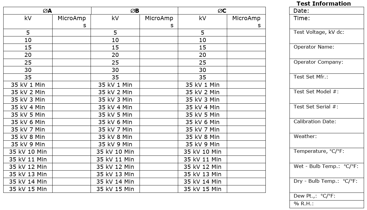
Form 2
| OVERPOTENTIAL TEST RESULTS
FOR 5 kV POWER CABLE | ||||
| Project Name: | Project Number: | Contractor P.O. #: | ||
| Contractor Name: | Circuit/Cable #: | Cable Mfr.: | ||
| Cable Length, Feet: | Aerial, Duct, or U/G: | # of Conductors per Cable: | ||
| Wire Size, AWG or MCM: | Shielded or Non-shielded: | Voltage Rating of Cable: | ||
| Insulation Type: | Insulation Thickness: | Pothead or Terminal Type: | ||
| Location, Indoor or Outdoor: | ||||
| Corona Suppression (Ionization Protection) Used, Yes/No | Type Used: | |||
| Test Set Guard Lead Used, Yes/No | Where Connected: | |||
| Contacts/Cable Cleaned Before Test, Yes/No | Cleaner Type: | |||
| List Associated Equip. Used:
| ||||
| Remarks:
| ||||
Test Information
| ÆA | ÆB | ÆC | Date: | |||||||
| kV | MicroAmps | kV | MicroAmps | kV | MicroAmps | Time: | ||||
| 5 | 5 | 5 | Test Voltage, kV dc: | |||||||
| 10 | 10 | 10 | ||||||||
| 15 | 15 | 15 | Operator Name: | |||||||
| 20 | 20 | 20 | ||||||||
| 25 | 25 | 25 | Operator Company: | |||||||
| 30 | 30 | 30 | ||||||||
| 35 | 35 | 35 | Test Set Mfr.: | |||||||
| 35 kV 1 Min | 35 kV 1 Min | 35 kV 1 Min | ||||||||
| 35 kV 2 Min | 35 kV 2 Min | 35 kV 2 Min | Test Set Model #: | |||||||
| 35 kV 3 Min | 35 kV 3 Min | 35 kV 3 Min | ||||||||
| 35 kV 4 Min | 35 kV 4 Min | 35 kV 4 Min | Test Set Serial #: | |||||||
| 35 kV 5 Min | 35 kV 5 Min | 35 kV 5 Min | ||||||||
| 35 kV 6 Min | 35 kV 6 Min | 35 kV 6 Min | Calibration Date: | |||||||
| 35 kV 7 Min | 35 kV 7 Min | 35 kV 7 Min | ||||||||
| 35 kV 8 Min | 35 kV 8 Min | 35 kV 8 Min | Weather: | |||||||
| 35 kV 9 Min | 35 kV 9 Min | 35 kV 9 Min | ||||||||
| 35 kV 10 Min | 35 kV 10 Min | 35 kV 10 Min | Temperature, °C/°F: | |||||||
| 35 kV 11 Min | 35 kV 11 Min | 35 kV 11 Min | ||||||||
| 35 kV 12 Min | 35 kV 12 Min | 35 kV 12 Min | Wet – Bulb Temp.: °C/°F: | |||||||
| 35 kV 13 Min | 35 kV 13 Min | 35 kV 13 Min | ||||||||
| 35 kV 14 Min | 35 kV 14 Min | 35 kV 14 Min | Dry – Bulb Temp.: °C/°F: | |||||||
| 35 kV 15 Min | 35 kV 15 Min | 35 kV 15 Min | ||||||||
| Dew Pt.,: °C/°F: | ||||||||||
| % R.H.: | ||||||||||
| _________________________________ | _______________________________ | |
| Contractor Superintendent/Date | Air Products Representative/Date |
Overpotential Test Results for 5 kV Power Cable
Click on Overpotential Test Results for 5 kV Power Cable (above)
for Excel Worksheet
Form 3
| OVERPOTENTIAL TEST RESULTS
FOR 8 kV POWER CABLE | ||||
| Project Name: | Project Number: | Contractor P.O. #: | ||
| Contractor Name: | Circuit/Cable #: | Cable Mfr.: | ||
| Cable Length, Feet: | Aerial, Duct, or U/G: | # of Conductors per Cable: | ||
| Wire Size, AWG or MCM: | Shielded or Non-shielded: | Voltage Rating of Cable: | ||
| Insulation Type: | Insulation Thickness: | Pothead or Terminal Type: | ||
| Location, Indoor or Outdoor: | ||||
| Corona Suppression (Ionization Protection) Used, Yes/No | Type Used: | |||
| Test Set Guard Lead Used, Yes/No | Where Connected: | |||
| Contacts/Cable Cleaned Before Test, Yes/No | Cleaner Type: | |||
| List Associated Equip. Used:
| ||||
| Remarks:
| ||||
Test Information
| ÆA | ÆB | ÆC | Date: | |||||||||||
| kV | MicroAmps | kV | MicroAmps | kV | MicroAmps | Time: | ||||||||
| 5 | 5 | 5 | Test Voltage, kV dc: | |||||||||||
| 10 | 10 | 10 | ||||||||||||
| 15 | 15 | 15 | Operator Name: | |||||||||||
| 20 | 20 | 20 | ||||||||||||
| 25 | 25 | 25 | Operator Company: | |||||||||||
| 30 | 30 | 30 | ||||||||||||
| 35 | 35 | 35 | Test Set Mfr.: | |||||||||||
| 40 | 40 | 40 | ||||||||||||
| 40 kV 1 Min | 40 kV 1 Min | 40 kV 1 Min | ||||||||||||
| 40 kV 2 Min | 40 kV 2 Min | 40 kV 2 Min | Test Set Model #: | |||||||||||
| 40 kV 3 Min | 40 kV 3 Min | 40 kV 3 Min | ||||||||||||
| 40 kV 4 Min | 40 kV 4 Min | 40 kV 4 Min | Test Set Serial #: | |||||||||||
| 40 kV 5 Min | 40 kV 5 Min | 40 kV 5 Min | ||||||||||||
| 40 kV 6 Min | 40 kV 6 Min | 40 kV 6 Min | Calibration Date: | |||||||||||
| 40 kV 7 Min | 40 kV 7 Min | 40 kV 7 Min | ||||||||||||
| 40 kV 8 Min | 40 kV 8 Min | 40 kV 8 Min | Weather: | |||||||||||
| 40 kV 9 Min | 40 kV 9 Min | 40 kV 9 Min | ||||||||||||
| 40 kV 10 Min | 40 kV 10 Min | 40 kV 10 Min | Temperature, °C/°F: | |||||||||||
| 40 kV 11 Min | 40 kV 11 Min | 40 kV 11 Min | ||||||||||||
| 40 kV 12 Min | 40 kV 12 Min | 40 kV 12 Min | Wet – Bulb Temp.: °C/°F: | |||||||||||
| 40 kV 13 Min | 40 kV 13 Min | 40 kV 13 Min | ||||||||||||
| 40 kV 14 Min | 40 kV 14 Min | 40 kV 14 Min | Dry – Bulb Temp.: °C/°F: | |||||||||||
| 40 kV 15 Min | 40 kV 15 Min | 40 kV 15 Min | ||||||||||||
| Dew Pt.,: °C/°F: | ||||||||||||||
| % R.H.: | ||||||||||||||
| _________________________________ | _______________________________ | |||||||||||||
| Contractor Superintendent/Date | Air Products Representative/Date | |||||||||||||
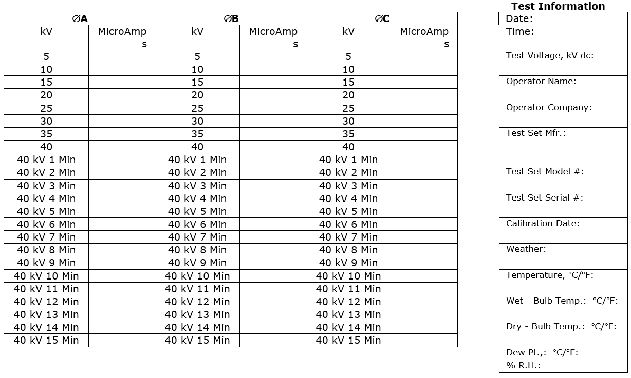
Overpotential Test Results for 8 kV Power Cable
Click on Overpotential Test Results for 8 kV Power Cable (above) for Excel Worksheet
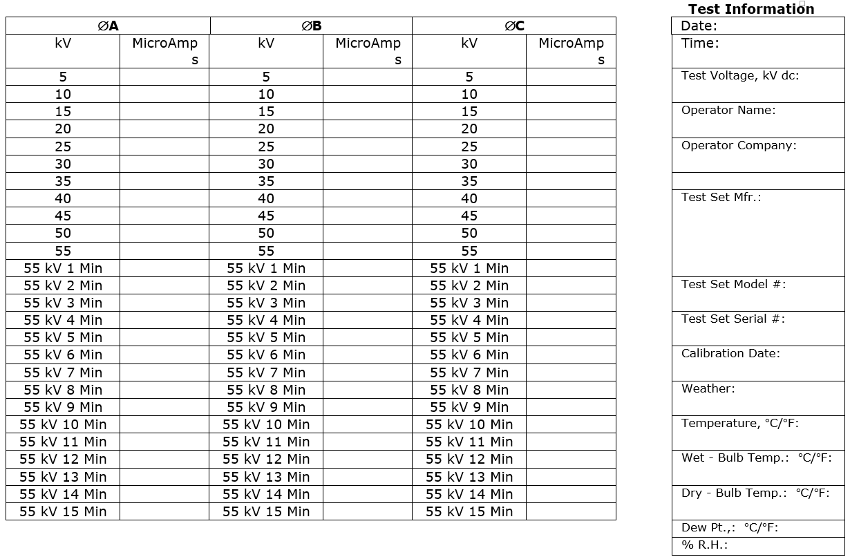
Form 4
| OVERPOTENTIAL TEST RESULTS
FOR 15 kV POWER CABLE | ||||
| Project Name: | Project Number: | Contractor P.O. #: | ||
| Contractor Name: | Circuit/Cable #: | Cable Mfr.: | ||
| Cable Length, Feet: | Aerial, Duct, or U/G: | # of Conductors per Cable: | ||
| Wire Size, AWG or MCM: | Shielded or Non-shielded: | Voltage Rating of Cable: | ||
| Insulation Type: | Insulation Thickness: | Pothead or Terminal Type: | ||
| Location, Indoor or Outdoor: | ||||
| Corona Suppression (Ionization Protection) Used, Yes/No | Type Used: | |||
| Test Set Guard Lead Used, Yes/No | Where Connected: | |||
| Contacts/Cable Cleaned Before Test, Yes/No | Cleaner Type: | |||
| List Associated Equip. Used:
| ||||
| Remarks:
| ||||
Test Information
| ÆA | ÆB | ÆC | Date: | |||||||
| kV | MicroAmps | kV | MicroAmps | kV | MicroAmps | Time: | ||||
| 5 | 5 | 5 | Test Voltage, kV dc: | |||||||
| 10 | 10 | 10 | ||||||||
| 15 | 15 | 15 | Operator Name: | |||||||
| 20 | 20 | 20 | ||||||||
| 25 | 25 | 25 | Operator Company: | |||||||
| 30 | 30 | 30 | ||||||||
| 35 | 35 | 35 | ||||||||
| 40 | 40 | 40 | Test Set Mfr.: | |||||||
| 45 | 45 | 45 | ||||||||
| 50 | 50 | 50 | ||||||||
| 55 | 55 | 55 | ||||||||
| 55 kV 1 Min | 55 kV 1 Min | 55 kV 1 Min | ||||||||
| 55 kV 2 Min | 55 kV 2 Min | 55 kV 2 Min | Test Set Model #: | |||||||
| 55 kV 3 Min | 55 kV 3 Min | 55 kV 3 Min | ||||||||
| 55 kV 4 Min | 55 kV 4 Min | 55 kV 4 Min | Test Set Serial #: | |||||||
| 55 kV 5 Min | 55 kV 5 Min | 55 kV 5 Min | ||||||||
| 55 kV 6 Min | 55 kV 6 Min | 55 kV 6 Min | Calibration Date: | |||||||
| 55 kV 7 Min | 55 kV 7 Min | 55 kV 7 Min | ||||||||
| 55 kV 8 Min | 55 kV 8 Min | 55 kV 8 Min | Weather: | |||||||
| 55 kV 9 Min | 55 kV 9 Min | 55 kV 9 Min | ||||||||
| 55 kV 10 Min | 55 kV 10 Min | 55 kV 10 Min | Temperature, °C/°F: | |||||||
| 55 kV 11 Min | 55 kV 11 Min | 55 kV 11 Min | ||||||||
| 55 kV 12 Min | 55 kV 12 Min | 55 kV 12 Min | Wet – Bulb Temp.: °C/°F: | |||||||
| 55 kV 13 Min | 55 kV 13 Min | 55 kV 13 Min | ||||||||
| 55 kV 14 Min | 55 kV 14 Min | 55 kV 14 Min | Dry – Bulb Temp.: °C/°F: | |||||||
| 55 kV 15 Min | 55 kV 15 Min | 55 kV 15 Min | ||||||||
| Dew Pt.,: °C/°F: | ||||||||||
| % R.H.: | ||||||||||
| _________________________________ | _______________________________ | |
| Contractor Superintendent/Date | Air Products Representative/Date |
Overpotential Test Results for 15 kV Power Cable
Click on Overpotential Test Results for 15 kV Power Cable (above) for Excel Worksheet
Figure 1
Medium Voltage Cable Hi-Pot Test Lead Connection Details
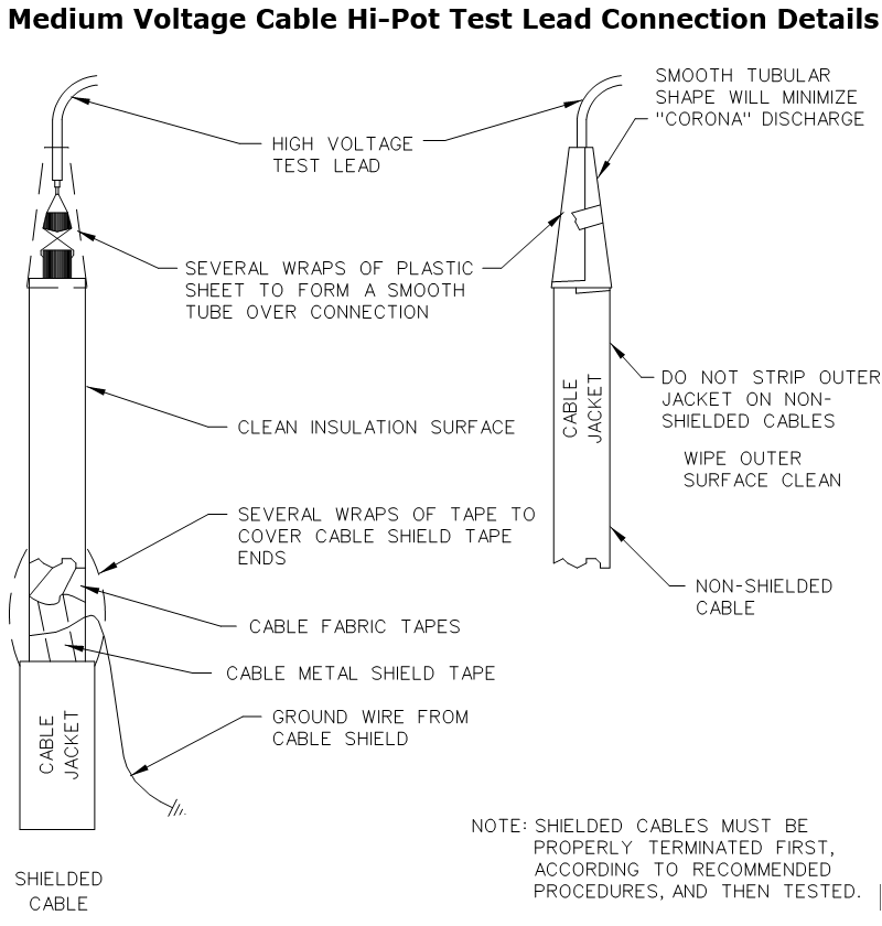
Figure 2
Methods of Reducing Corona at Medium Voltage Cable Ends for Testing
