1.0 PURPOSE
2.0 SCOPE
3.0 APPLICABLE DOCUMENTS
4.0 RESPONSIBILITY
5.0 MANPOWER
6.0 TOOLS & EQUIPMENT
7.0 METHODS/PROCEDURES
8.0 QUALITY CONTROL
9.0 SAFETY PRECAUTION
10.0 ATTACHMENT.
1.0 PURPOSE
This method statement will serve as a minimum guideline to carry out the erection / Installation of Tail Gas Compressor for Plants and Refinery Projects.
2.0 SCOPE
This Method statement will cover the minimum requirements for Installation of Tail Gas Compressor to be applied at the site for for Plants and Refinery Projects.
3.0 APPLICABLE DOCUMENTS
3.1 Specification and Standards
3.1.1 S-000-1630-003 Material and Equipment Protection Program at work Site.
3.1.2 S-000-1520-103 Handling Procedure.
3.1.3 S-000-1640-005 Procedure for Work Release Between Disciplines.
3.1.4 S-000-1520-102 Non-Conformity Control Procedure.
3.1.5 S-000-1520-001 Field QC Procedure.
3.1.6 S-000-1650-001 Safety Execution plan.
3.1.7 FWBS CODE (5000) Equipment Installation.
3.2 ARAMCO Specification and Standards
3.2.1 SAEP-302 Instruction for obtaining a waiver of mandatory Saudi ARAMCO Engineering requirements.
3.2.2 SAES-Q-010 Cement Based Non-shrink Grout for Structural and Equipment Grouting.
3.2.3 SAES-L-350 Construction of Plant piping.
3.2.4 SAES-K-403 Reciprocating Compressors.
3.2.5 SAIC-M-2006 Inspection of Support Foundation Prior to Structural or Equipment Installation.
3.2.6 SAIC-K-2004 Mounting Plate Installation and Leveling for Compressors.
3.2.7 SAIC-K-2008 Final Compressor / Driver Aligmnent.
4.0 RESPONSIBILITY
4.1 Construction Manager shall be responsible for all HSE matters, Analyze and schedule all construction activities with his department to include manpower and equipment line up as well as other possible resources required for the successful implementation of the construction work activities. Study all aspects of work procedure as per Technical Scope of Work.
4.2 Mechanical Superintendent/Supervisor shall review all necessary documents for the Erection works in his area to include, technical scope of work, specification, bill of quantities, planned milestone dates and construction procedure in support to his Mechanical Foreman. He shall monitor the availability of materials in accordance with the schedules and construction analysis. He shall directly report to the Construction Manager. Coordinate with the other disciplines to visualize possible conflicts in the drawings as well as in the schedules to provide other options in preventing unnecessary delays and obstructions.
4.3 Mechanical foreman shall be responsible for the direct work supervision at site and ensure the work is performed in accordance with JGC/DAEWOO Technical Scope of Work and latest approved for construction drawings. He shall monitor the availability of materials in line with his required schedule.
4.4 QC Inspector shall be responsible for monitoring and inspection of the work and ensure that the work is performed in accordance with JGC/DAEWOO Technical Scope of Work and Standards.
4.5 Field Supervisor shall be responsible for monitoring safety aspects and ensuring that the work is done in accordance with JGC/DAEWOO Safety Standard Procedure, he shall discuss with the workers the characteristics of related materials and status of work area giving reminders as an additional point to work safely.
5.0 MANPOWER
5.1 QC Inspector shall be directly reporting to QC Supervisor in accordance to schedule Q.
5.2 Safety Engineer
5.3 The Millwright Supervisor shall control the overall activity of equipment installation. The basic manpower under him shall consist but not limited to the following:
5.3.1 Foreman Millwright
5.3.2 Millwright.
5.3.3 Mechanical Fitters.
5.3.4 Rigger (Aramco Certified).
5.3.5 Crane Operator (Aramco Certified).
5.3.6 Masons/Carpenters.
5.3.7 Truck Driver.
5.3.8 Helper.
5.3.9 Welder.
5.3.10 Surveyor.
6.0 TOOLS AND EQUIPMENT
6.1 Tools and equipment needed should be in good condition and must be checked by competent person and respective supervisor prior to use in the plant. Third Party vehicle and equipment inspections and vehicle stickers required. Saudi Aramco certified where required. These includes but not limited to:
6.1.1 Calibrated engineering level with calibration certificate.
6.1.2 Corrective wrenches all required range.
6.1.3 Crane.
6.1.4 Certified sling and hoists.
6.1.5 Chipping hammer/bush hammer.
6.1.6 Welding Machine.
6 .1. 7 Compressor.
6.1.8 Calibrated Alignment and Leveling tools (Dial indicator, precision master level, other measuring equipment); Final shaft alignment shall be as per Vendor’s Recommended method.
6.1.9 Low-height rampackjacks.
6.1.10 Chain block.
6.1.11 Vendor-supplied tools, if any.
6.1.12 Rubber mallet.
6.1.13 Hydraulic Jack.
6.1.14 Pully.
7.0 METHODS / PROCEDURES
7.1 Jobsite Receiving and Inspection:
7.1.1 Upon withdrawal all requirements of storage at site shall be incorporate into the site preservation plan and adhered to in all respects and receipt of equipment from warehouse, receiving inspection shall be conducted immediately as per applicable SA TIP and SAIC-K-2011 to verify compliance and latest revision of vendors drawing.
7.1.2 Record of inspection shall be documented as per applicable SATIP and SAIC (Material Receiving Inspection); findings and deviations shall be documented in Quality control Inspection Report (QCIR) and Non Conformance Report (NCR).
7.2 Equipment Preservation/Protection:
7.2.1 Vendor’s/Manufacture’s recommendation for equipment preservation shall be followed applicable provision for S-000-1630-003(Material and Equipment Protection Program)
7.2.2 Equipment Rust Preservation shall be done using applicable vendor’s/manufacturer’s documents.
7.2.3 When the equipment arrived at site, shop preservation shall be checked, where necessary damage to preservation shall be rectified without delay.
7.3 Preparatory Works:
7.3.1 Secure work permit and other applicable approved documents prior to work commence.
7.3.2 Tools and equipment shall be made operational and available for use. Ensure tools are color-coded accordingly.
7.3.3 Conduct lifting study & get approved lifting plan accordance with G.I.7.028 for required cases.
7.3.4 Prior to the arrival of equipment on site, Contractor shall review the manufacturer’s requirement and the requirements of this specification regarding on site storage of the equipment. These requirements shall be incorporated to site preservation plan and adhere to in all respects.
7.3.5 Install barricades to confine the area for authorized personnel only.
7.4 Check for Foundation and Foundation Chipping
7.4.1 Prior to starting installation work, the person in charge of construction of foundation should be requested to check whether the strength of the foundation is sufficient.
7.4.2 Then check the location and size of anchor boxes of foundation according to the foundation drawing(V-2158-222-A-221).
7.4.3 Determine the accurate centerlines for installation of the compressor train.( etc., refer to the reference point which has been set in construction).
7.4.4 Determine centerlines for installation of the auxiliary equipment referring to the centerlines of the foundation for the compressor. Mark the centerlines on the side of the foundation.
7.4.5 Flatness and level should be measured at the points where liners are to be installed.
7.4.6 In order to obtain a satisfactory bounding effect, the top surface of the foundation, which is to be grounded, is sufficiently chipped to remove completely hair cracks, porosities and laitance, etc. Chipping must be done to the specified level indicated on the foundation drawing. It is desirable to carry out chipping by using a cold chisel in order to obtain a finer roughed surface. Coarse roughing by means of air chisel should be avoided as it may damage the foundation concrete. The grouting thickness is shown on the foundation drawing.
7.4.7 After chipping of the foundation, clean the surface of the foundation. Confirm acceptances & turnover of civil works foundation/pedestals with a signed copy of works release notice.
7.5 Installation of Liner
7.5.1 Installation of liner is based on Vendor’s Installation Liner List (Refer to attachment A. Vendor’s Installation List).
7.5.2 Liner plate for jack bolt must be installed as per foundation drawing.
7.6 Installation of Tail Gas Compressor
7.6.1 Skidding
(1) Assembly of Temporary rail
Installation of anchor bolt and grout for temporary rail foundation and survey.
Remove the structure and handrail for access of temporary rail and access of frame for the installation of compressor to correct position and elevation and alignment.
Lifting the frame and install roller on the temporary rail. Adjust hillman roller top of the temporary rail.
– Area should be clean and barricaded, provide complete work permit in preparation for lifting.
(2) Loading Compressor on the Temporary rail
– Prepare all lifting gear certificate by third party and approval rigging plan by Saudi ARAMCO.
– Using 250tons crane in lifting compressor frame on temporary rail ensure that the crane is in good condition. All lifting gear certification and rigging plan must be checked by competent person respective supervisor prior to implementation of lifting activity.
(3) Pre-assembly Main motor to Compressor Base Frame
– Lifting location and crane shall be on positioned and set all lifting gear shall be protected by wooden blocks, rubber or other suitable material that will prevent from damages.
– Lifting Tail Gas Compressor main motor on base frame.
Bolt tightening main motor with compressor base frame.
7.6.2 Jack Down
Installation sequence is based on Vendor’s installation Manual and Supervision (Refer to attachment B, Vendor’s Installation Procedure).
(1) Pulling Foundation on Position
Prepare all tools for frame and compressor pulling( wire rope, pulley, shackle..).
– Connect wire rope to lifting lug and pulling base frame to gear box center line.
(2) Jack up Skid for removal of roller and Temporary beam
– 100 tons and 50 tons hydraulic jack set on concrete foundation and jack up for removal of temporary rail frame beam.
– Hydraulic jack control up to 20mm or 40mm for removal of roller and install stool under the compressor skid and release hydraulic jack.
– Remove temporary rail frame and roller
(3) Jack Down
– Jack up for lifting compressor skid, setting stools frame on jack bolt position and tightening jack bolt.
– Jack down for necessary height of compressor and it’s position, alignment until touch pad plate.
– Structure and handrail shall be re-install and inspect.
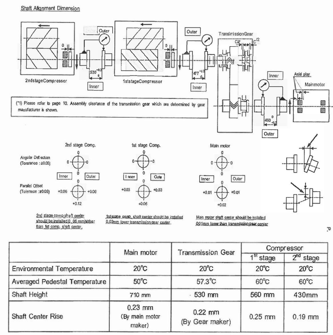
7.7 Alignment of Compressor
7.7.1 On installation, the compressor transmission gear and main motor should be checked for alignment, and it should be corrected, if necessary.
7.7.2 Alignment should be done with the rotor of the compressor, transmission gear and main motor shift to the operating position.
7.7.3 On the coupling hubs measure shaft misalignment and parallelism of surfaces by a dial gauge. Correct the alignment, if it doesn’t within the range shown on ” Installation Dimension”.
7. 7.4 Correction of alignment should be done by shims inserted between the baseplates and the machines. The jack screws equipped to the machines are available for shim adjustment.
7.7.5 Record the final values of the alignment measurement.
7.8 Grouting
7.8.1 Following items shall be considered before grouting execution:
(1) Prior to grouting, concrete repair have been performed in accordance with SAIC-Q-1062 as based on SAER-5803.
(2) Grout shall be mixed as per the Grout Manufacturer’s instructions.
(3) Foundation preparation shall be in accordance with the grout manufacturer’s written instructions.
(4) Concrete foundations shall be cured for a minimum of 7 days before surface preparations for grouting.
(5) Laitance, oil-soaked or damaged concrete shall be removed down to sound concrete by chipping to the level of sound fractured aggregate or to a minimum of the top !inch (25mm) of the concrete.
(6) All dust and loose particles shall be removed with clean, dry, oil free compressed air. (7) Grout Formwork, where required, shall be constructed with adequate strength, rigidity and required dimensions to permit grout placement and avoid leakage.
(8) A bond breaker shall be applied to the formwork that will be in contact with the grout. (9) After cleaning, the foundation shall be protected with 0.15mm polyethylene sheeting to prevent contamination.
(10) Concrete surfaces in contact with the grout shall be saturated with clean water before grout placement. The surface shall be damp but free from standing water.
(11) Joints in the grout shall be located as shown in the drawings or as recommended by the manufacturer.
(12) Grout shall be placed in only one direction to prevent trapping air; Grouting shall
be quick and continuous to avoid segregation, bleeding or premature initial set.
(13) Re-tempering of grout adding water after stiffening is not permitted.
(14) If the grout is placed through grout holes, it shall be placed from one hole continuously until the grout has passed a second hole. A liquid head pressure shall be maintained at the first access hole until a head pressure is established at the second hole and continued in a similar fashion until the next hole.
(15) Grout shall be mixed, placed and cured in accordance with manufacturer’s written requirements. The contractor shall read, understand and comply with the manufacturer’s instructions as printed on each unit.
(16) The grout shall be cut back to the lower edge of the base plate by 45″ angle unless otherwise indicated.
17) The grout shall be checked for voids after the gout has cured. Any voids shall filled according to manufacturer’s recommendations.
8.0 QUALITY CONTROL
8.1 QC Personnel shall be assigned to ensure the quality control and assurance requirement of the project.
8.2 Inspector shall be responsible to conduct all required inspection/documentations to ensure it complies with SAIC/SATIP.
8.3 Contractor has to utilize the applicable SAIC for every activity.
8.4 Mill test reports for the structural materials are furnished and verify to conform to the requirements of the applicable specification.
8.5 Calibration shall be done as required for all machines and tools going to be used in the work in accordance with schedule Q.
9.0 SAFETY PRECAUTION
9.1 Obtain the approval of the work permit and required applicable documents from the concerned Representative before starting any work.
9.2 Work execution shall be carried out in accordance with method statement, and in compliance with Saudi ARAMCO General Instruction G.1.7.028, Crane Lifts; Types and Procedure.
9.3 Continuous monitoring and inspection shall be implemented to detect and correct unsafe practices while performing the work activities.
9.4 Provide warning sign and sufficient barricade on working area and only assigned personnel will be allowed in the area.
9.5 Machinery like grinding wheel cutter shall have a protection method
9.6 All workers shall wear as a minimum PPE required below.
9.6.1 Safety Helmet
9.6.2 Safety Glasses
9.6.3 Safety Shoes
9.6.4 Gloves
9.6.5 Mask, if required to prevent inhalation of dust and welding gas
9.6.6 Ear plug, if required by conditions.
9.7 Safety shall be requested and carried out in accordance with safety procedure
9.8 All Rigging Equipment shall be in good condition and possess a valid certification from authorized certifying and inspection depar1ments, in compliance with Saudi ARAMCO General Instruction G.I.7.030 Inspection and Testing Requirements of Elevating/Lifting Equipment.
9.9 Field Supervisor shall monitor the work activities to help and to protect all assigned workers against exposure of safety hazards. He shall ensure that Personal Protective Equipment (PPE’s) are supplied and used and comply with the JGC/DAEWOO applicable standards.
9.10 Housekeeping shall be maintained and working area shall be kept in a clean and tidy manner.
9.11 Job Hazard and Risk Assessment (JHRA) of this method statement shall be disseminated and explained to workers for safety awareness.
10.0 ATTACHMENT
Installation Liner List
Installation Procedure
Job Safety Analysis