1. SCOPE ………………………………………..2. REFERENCE
3. DEFINITIONS
4. GENERAL REQUIREMENTS …………4.1 General
4.2
Submittal
4.3 Delivery
Inspection
……………………
4.4
Handling and Storage
5.
INSTALLATION REQUIREMENTS
5.1 General
…………………………………..
5.2
Above Ground Pipe Installation
5.3
Underground Pipe Installation
6. FIELD JOINING …………………………….6.1 General
6.2
Joiner Qualification
6.3 Adhesive
Bonded
Joints
…………….
6.4
Laminated Joints
6.5 Gasket Sealed Joints
6.6 Flanged
Joints
………………………….
7. TESTING 7.1
Soil Testing
7.2 Hydrotesting
…………………………….
7.3
Joint Testing
FIGURE’1
1. Scope
1.1 This Standard establishes the requirements for installation of above ground and underground
Fiberglass Reinforced Plastic (FRP) piping systems and components for use in SABIC facilities.
1.2 The requirements described herein apply to a variety of commodity and custom pipe systems,
including joints, fittings and supports, as designed in accordance with SES P01-E28, design requirements
for FRP piping systems. Installation of FRP piping not covered by the requirements of SES P01-E28 or
special installations not specifically discussed herein are considered outside the scope of this Standard.
1.3 The provisions of this Standard shall be considered minimum requirements. Manufacturer’s installation
recommendations or requirements and other applicable SABIC Standards and specifications shall also be
followed. In case of conflict between documents, the most stringent requirement shall govern.
2. Reference
Reference is made in this Standard to the following documents. The latest issue, amendments and
supplements to these documents shall apply unless otherwise indicated.
SABIC Engineering Standards (SES)
Z05-S01 General Procurement Guidelines
P14-T02 Quality Assurance of FRP Piping
P01-E28 Design Requirements for FRP Piping Systems
American Society for Testing and Materials (ASTM)
D 883 Standard Terminology Relating to Plastics
D 1587 Standard Practice for Thin-Walled Tube Sampling of Soils
D 2166 Standard Test Method for Unconfined Compressive Strength of Cohesive Soil
D 2487 Standard Test Method for Classification of Soils for Engineering Purposes
D 2488 Standard Practice for Description and Identification of Soils
D 3839 Standard Practice for Underground Installation of Fiberglass Pipe
American Society of Mechanical Engineers (ASME)
B 31.3 Chemical Plant and Petroleum Refinery Piping
American Water Works Association (AWWA)
M45 Manual of Water Supply Practices, Fiberglass Pipe Design
3. Definitions
For the purpose of understanding this Standard, the following definitions apply. Additional definitions
relating to FRP equipment are per ASTM D 883, or other standards as referenced.
Axial. The longitudinal axis of the pipe.
Commodity Pipe. FRP pipe manufactured in standard sizes and classes for general use.
Contractor. The party responsible for all or part of the design, engineering, procurement, construction and
commissioning for a project.
Corrosion Liner. The thickness of the non-structural layer(s) on the interior of the pipe wall laminate
intended to resist degradation by the service fluid, thereby protecting the structural laminate. The pipe wall
laminate typically consists of the corrosion liner plus the structural wall.
Custom Pipe. FRP pipe manufactured for project specific requirements.
Designer. General term referring to the party employed or contracted by the contractor for design of the
piping system in accordance with SES P01-E28.
Design Report. Documentation of the pipe design prepared in compliance with SES P01-E28. Includes
summaries of design conditions, burial conditions, pipe and component construction data, support
locations and loads, and other data essential to the installation.
Field Joining Contractor. The party responsible for the field joining of the FRP pipe, spool assemblies
and components. This may be the contractor, but typically it is a specialty subcontractor with specific
training and experience in the joining system being used.
Hoop. Circumferential direction in the pipe.
Manufacturer. The party which manufactures FRP pipe and components and is responsible for the
qualification testing of the product.
Material Manufacturer. The supplier of the raw materials used for manufacturing of the FRP pipe and
components.
Native Soil. The soil which exists in the area of the underground pipe installation.
Shear Collar. An FRP laminate applied to the exterior of the pipe adjacent to anchors or other pipe
supports for the purpose of transferring axial pipe loads into the supporting structure.
Structural Wall. The thickness of the pipe wall laminate which is reinforced and provides load bearing
capability, but does not include the corrosion liner thickness. The pipe wall laminate typically consists of the
corrosion liner plus the structural wall.
4. General Requirements
4.1 General
The contractor is responsible to compile data from the design report, manufacturer’s data, and all other
information required to perform a proper installation. This information shall be summarized and prepared
for submittal of installation procedures as detailed below.
Quality control of the installation is the responsibility of the contractor. Minimum requirements are per SES
P14-T02 and as described herein.
4.2 Submittal
Prior to installation of FRP pipe, spool assemblies or components, contractor shall submit for approval an
installation specification which defines the intended implementation of all installation requirements. This
shall include, but not necessarily be limited to the following information.
4.2.1 Summary of design report data needed for installation:
a. Installation temperature range
b. Soil classification
c. Test pressure
d. Piping drawings with support types and locations
e. Expected displacements
f. Support loads
4.2.2 Manufacturing data:
a. Materials
b. Construction details
c. Dimensions
4.2.3 Joining procedures:
a. Bonding procedure specification
b. Joiner certifications
c. Manufacturer’s joining recommendations and requirements
d. Methods of controlling environmental issues in joining area
4.2.4 Installation procedures:
a. Manufacturer’s installation requirements
b. Control of installation temperature
c. Protection of existing facilities
d. Above ground piping
(i) Support design and fabrication
(ii) Temporary support
e. Underground piping
(i) Excavation plan
(ii) De-watering plan
(iii) Flotation prevention
(iv) Backfill source
(vii) Compaction methods
4.2.5 Quality Control plan
a. Requirements from SES P14-T02
b Verification of general installation issues per standard practice
(i) Lines and grades
(ii) Support types, locations, clearances
(ii) Trench dimensions, foundation, bedding and backfill materials, compaction
c. Additional field monitoring of UG installation
(i)
In-place density testing
(ii) Pipe deflection monitoring
(III) Hydrotesting
4.3 Delivery inspection
4.3.1 Defect Evaluation and Acceptance Criteria:
a.
It is assumed that pipe and fittings have been correctly manufactured and inspected prior to
shipment. If inspection for manufacturing compliance is needed, it shall be accomplished by qualified
personnel in accordance with SES P14-T02.
b. Inspect pipe, spools and components for shipping and handling damage. Investigate damaged
or displaced packing for its potential effect on the pipe and components.
c. Inspect interior surfaces to the extent accessible. Impact damage is often apparent as star
fractures on interior surfaces even in the absence of evidence on the exterior.
d. Remove temporary protection on flanges, spigots, bells and couplings and inspect sealing
surfaces and gaskets for scratches, cuts or other damage that could compromise sealing. Replace
protectors until final connections are made.
e. Inspect adhesive bonding kits or laminated joint materials to verify that all necessary materials
are included, not leaking or visibly damaged, and that at least 6 months shelf life remains before
expiration.
4.3.2 Corrective Action and Repairs
a. If damaged areas are identified, they may be removed from the pipe or component by cutting and
removing a length sufficient to remove all affected areas. Rejoining shall be in a manner approved by
SABIC and the manufacturer.
b. Depending on the extent, location and type of damage, repairs may be implemented only with the
approval of SABIC. In all cases, repairs shall be completed in accordance with the requirements of the
manufacturer.
4.3.3 Documentation
All damaged areas and repairs shall be documented completely and incorporated into the QC
inspection records.
4.4 Handling and Storage
All handling, lifting and storage of pipe, spools, fittings, joint materials and other components shall be
in accordance with the requirements of the manufacturer. In addition, the following minimum
requirements shall be followed:
All protective covers on flanges, spigots, bells or couplings shall remain in place during handling and
storage.
4.4.1 Lifting and Handling
a. Pipe, fittings and spool assemblies shall not be rolled, slid, dropped, allowed to swing into other
objects, or forced out of shape.
b. Care shall be exercised to prevent tools, scaffolding, or other objects from striking or being
dropped on or inside the pipe, fittings or spool assemblies.
c. Pipe, fittings and spool assemblies shall be lifted and positioned using proper rigging and hoisting
practices.
d. If allowed by the manufacturer, multiple lengths of pipe joined by the adhesive bonded or
laminated joint methods may be lifted into position as an assembly. Maximum distance between lifting
points shall be as specified by the manufacturer.
e. For assembled spools containing a change in direction or branch line, lifting spans must be
adjusted to account for the additional weight.
f. Adhesive bonded and laminated joints shall be cured to the extent required by the manufacturer
before moving or lifting assemblies.
g. Lifting sling angle shall not be more than 45 degrees from vertical.
h. Lifting slings that will be in direct contact with the pipe, spool assemblies and components shall
be made from woven nylon or canvas and shall be a minimum of 3 in. wide.
i. Care shall be exercised to prevent shackles, eyes, hooks, etc. from coming into contact with the
pipe, fittings and spool assemblies.
j.
Lifting slings shall not be attached to, or allowed to come in contact with nozzles, flanges,
gussets, or other fittings.
k.
If straight pipe lengths are received with smaller pipe sizes nested inside of larger pipes, special
precautions as recommended by the manufacturer shall be followed to avoid damage to the interior
surfaces.
4.4.2 Storage
a. Pipe and spool assemblies shall be supported for storage on level ground in the original shipping
cradles or equivalent, spaced no greater than 20 ft. and within 2 ft. of the pipe end.
b. Cradles used to support pipe, fittings and spool assemblies larger than 300 mm diameter shall
contact at least 120 degrees of the circumference, be padded, and match the outside diameter within
+1/8”, -0”.
c.
If pipe is stacked in layers, inverted cradles shall also be used on top of the pipe, and the support
cradles of various layers shall be aligned vertically. Stacking shall follow the requirements of the pipe
manufacturer.
d. Secure pipe and spool assemblies to prevent damage from wind.
e. Adhesive bonding and laminated joint reinforcement materials, resin and chemicals shall be
stored in the original packaging, in a dry area and within the temperature and humidity limits
recommended by the material manufacturers.
f. Resin, catalyst and chemical storage shall be outside the work area in approved areas.
g. Ancillary materials such as gaskets, locking strips and lubricants shall be stored in accordance
with the manufacturer’s recommendations.
5.Installation Requirements
5.1 General
5.1.1 This Standard describes the minimum requirements for installation of FRP piping systems.
Installation shall also comply with all recommendations and requirements of the piping manufacturer. In
case of conflict between documents, the most stringent requirement shall govern.
5.1.2 Maintain installation temperature range during final positioning, anchoring or burial of the pipe in
accordance with the design assumptions, as documented in the design report. The average pipe wall
temperature shall be used for this purpose.
5.1.3 Joining methods shall be in accordance with the manufacturer’s requirements and the additional
minimum requirements of Section 6 of this Standard.
5.1.4 Do not distort or bend pipe or fittings to achieve changes in direction or alignment of connections.
5.2 Above Ground Pipe Installation
5.2.1 General
a. Pipe shall be installed to the lines and elevations as shown on the approved drawings.
b. FRP pipe shall be protected with saddle supports at all points of contact with the supporting
structure.
c. Standard construction practices shall apply to verification of FRP pipe installation for compliance
with the installation specifications, lines and elevations, fit-up tolerances, connections and other
common practices. Routine inspection during progress of the work shall be performed to ensure
proper installation.
5.2.2 Supports
a. Support Types
(i) Simple Sliding Supports. Support vertical loads only and do not prevent lateral movement, uplift
or rotation.
(ii) Guides. Support vertical loads and restrain lateral movement; vertical uplift is sometimes
restrained. Axial movement is allowed and lateral movement is allowed to the extent of the gaps
between the support base and the guide clips attached to the supporting structure.
(iii) Anchors. Support vertical loads and prevent lateral movement, axial movement and uplift.
Rotation may be restrained to some extent, depending on the method of attachment to the supporting
structure. Axial loads are transmitted to the support by use of shear collars attached to the pipe on
each side of the anchor.
(iv) Other supports. Several variations of the basic supports are often used in FRP piping systems,
which most often utilize special configurations but accomplish the same basic function as the basic
support types listed.
b. Location
(i) Supports of the proper type shall be installed at the locations indicated on the drawings supplied
as a part of the design report.
(ii) Supports shall be centered on the supporting structure such that equal displacement length is
available in both directions.
(iii) Supports shall normally be located on straight pipe sections where outside diameter is
consistent. Do not install supports on fittings, joints or other uneven areas which could prevent a
proper fit of the support saddle, except for special supports designed specifically for the location.
(iv) Heavy equipment such as valves and actuators shall be supported independently from the
piping, except as allowed by the piping manufacturer or as detailed in the design report.
(v) Supports shall be located to not exceed the allowable support spans as specified by the pipe
manufacturer, except where explicitly directed in the design report.
c. Shear collars
(i) Shear collars are necessary on both sides of pipe anchors in horizontal runs, as well as above
supports in vertical pipe runs if used to support gravity loads. Shear collars are typically bonded
directly to the pipe and must be designed to transfer the axial pipe loads into the anchor or vertical
pipe support.
(ii) Shear collars preferably are FRP laminates applied directly to the pipe surface in accordance
with the procedures used for laminated joints in Section 6.4. Alternately, pipe manufacturers may
provide prefabricated collars in 180° sections which are bonded to the outside of the pipe adjacent to
the anchor or vertical pipe support. Manufacturer’s bonding procedures shall be followed, in
compliance with the applicable portions of Section 6 of this Standard.
d. Minimum Dimensions
(i) Support saddles shall be curved and fitted to the bottom 180° of the pipe. Similar protective
saddles shall also be fitted to the top half of the pipe when uplift or contact is anticipated.
(ii) Support saddles shall have a minimum width (length in the pipe axial direction) of one half of the
pipe diameter.
(iii) For pipe diameters larger than 4 in, the support saddles shall be steel that is lined with an
elastomeric material.
e. Fabrication and Installation Tolerances
(i) Support saddles shall be fabricated specifically to match the outside diameter of the FRP pipe,
considering the thickness of elastomeric liners and fabrication tolerances of both the pipe and support
saddle. In no case shall the support saddle cause distortion of the FRP pipe due to a poor fit or
clamping forces.
(ii) Additional layers of elastomeric material may be used to fill gaps between the support saddle and
the pipe surface.
f. Temporary Supports
(iv) Temporary structures may be used for lifting or during installation as required to position and
support the pipe before final supports and joints are in place. Temporary supports shall be sufficiently
wide and cushioned as needed to protect the pipe from damage. All temporary support structures
shall be removed prior to testing or operation of the piping.
5.2.3 Protection
a. FRP piping shall be protected from construction or operational conditions that could potentially
cause damage.
b. Heat sources shall be reviewed for their range over the long term and appropriate action taken to
avoid any adverse effect on the FRP pipe.
c. Vibration from connecting equipment, adjacent piping, or supporting structures shall be
eliminated or isolated from the FRP piping.
d. Point loads or contact from other structures or equipment that could potentially be abrasive to
the exterior of the pipe are not allowed.
5.2.4 Connection to Equipment
a. The typical connection of FRP piping to equipment or pipe of other materials is through the use
of flanges. Flanges shall match the standard drilling patterns used on the project.
b. Full faced flanges shall not be mated directly to raised face flanges or other configurations which
would cause bending in the FRP flange as bolts are tightened.
c. Vanstone style flanges with steel backing rings may be used where rotational adjustment is
desired or for direct mating to raised face or similar flange styles.
d. Bolting material specification shall be per the standard requirements of the project.
e. Flange bolting procedure, materials and other requirements are per Section 6.6.
5.3 Underground Pipe Installation
5.3.1 General
a. This Standard establishes guidelines and procedures for the burial of FRP pipe in pressure and
non-pressure applications. The design of FRP piping in accordance with SES PO1-E28 requires that
support from the surrounding soil be provided through proper installation.
b. Guidelines and procedures are suggested for soil conditions typically encountered. Not all
possible combinations of pipe, soil types and site conditions that may occur are considered.
Installation procedures may need to be modified or expanded to meet the needs of the project. For
example, very small diameter pipes are generally so stiff that adherence to less stringent guidelines
may be appropriate, while very large diameter pipes can be so flexible that extraordinary care beyond
the scope of this Standard are required.
c. The contractor should rely on the pipe designer to fully describe the installation requirements
used as the basis for design of the pipe. These requirements are provided as part of the design report
or installation specification in accordance with SES PO1-E28, but coordination with the designer
during the design of the pipe and continued coordination with the designer during installation will be
necessary to ensure a practical and satisfactory installation.
d. Related standards that should be used for reference and clarification are:
i) SES PO1-E28, “Design Requirements for FRP Piping Systems”
(ii) American Water Works Association Manual M45, “Fiberglass Pipe Design”
(iii) ASTM D 3839, “Standard Practice for Underground Installation of Fiberglass Pipe”
e. Fiberglass pipe manufacturers typically provide installation procedures that are specific to their
products and must be considered and incorporated when installing the pipe. The final procedure used
for installation of the pipe shall meet or exceed the requirements of this Standard.
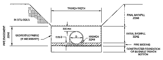
f. The following diagram defines the general terminology used throughout this Standard.
Figure
5.3.2 In-Situ Soils
a. Verify Native Soil Assumptions. It is important to determine the in-situ conditions prior to
construction to verify design assumptions and plan construction methods. In-situ soil conditions can
have a significant impact on the pipe design and its long-term performance. It is the contractor’s
responsibility to ensure that the assumptions and requirements regarding in-situ conditions made
during design of the pipe are satisfied.
b. Confirm Classification is Consistent with Design. Classification of the soils according to ASTM D
2487 and D 2488 is necessary to understand and verify in-situ conditions. Testing for properties of the
in-situ soils should be done frequently, particularly where changes are suspected. The properties of
importance are those at the pipe foundation and at the pipe embedment zone elevation. The
properties must represent the “weakest” condition expected to exist and consideration should be
given to seasonable variations.
c. As a minimum, the “blow count” for granular soils in accordance with ASTM D 1587 and the
unconfined compressive strength for cohesive soils in accordance with ASTM D 2166 shall be
determined.
5.3.3 Backfill / Embedment Materials
a. General. The soil overburden and live loads on an FRP pipe cause a decrease in the vertical
diameter and an increase in the horizontal diameter. The horizontal movement causes a passive
resistance in the side fill that helps support the pipe. Therefore, much emphasis is placed on the
selection of the backfill material and its compaction in the pipe embedment zone. The degree of
support provided by the backfill is dependent on the backfill material and compaction density to
achieve the soil stiffness required in the pipe design. The soil stiffness is also affected by the in-situ
soil properties. In relatively narrow cut trenches the effective stiffness of the soil supporting the pipe is
reduced when in-situ soils are loose or soft relative to the backfill and increased when in-situ soils are
dense or hard.
b. Classification of Material. Most coarse-grained soils as defined by ASTM D 2487 are suitable for
bedding and backfill of FRP pipe. Generally, granular soils containing fewer fines (percent passing the
U.S. Standard sieve No. 200) provide the required soil stiffness with less installation effort and the
least compactive energy. AWWA M45 and
c. ASTM D 3839 provide discussion and guidelines regarding suitable embedment materials in
terms that can be directly related to the pipe design.
d. Migration of Fines. In installations when an open-graded backfill material is placed adjacent to
finer in-situ material and where groundwater flow or fluctuations in the seasonal water table is
expected, migration of fines into the coarser material can occur. Experience has shown that migration
can result in significant loss of pipe support. In these situations methods must be employed to impede
migration such as use of a soil filter or geotextile filter fabric.
e. Installation Parameters. During the design of the pipe, several decisions and assumptions are
made regarding the backfill material and other parameters related to the support of the pipe. These
include:
(i) Backfill type
(ii) Compaction density
(iii) In-situ soil properties
(iv) Trench width
(v) Groundwater conditions
f. The contractor must ensure that these parameters and any other requirements of the design are
achieved or maintained throughout installation of the pipe. Any deviation or revision shall not be
allowed without carefully examining the impact on the pipe design.
5.3.4 Trench Excavation
a. Groundwater Control
(i) The installation of pipe in flooded trenches and in standing or running water conditions is beyond
the scope of this Standard. Water shall be removed from the trench before laying and backfilling the
pipe. Proper drainage for excavated and adjacent areas should be maintained to prevent the ponding
of water and excavated areas must be kept dry by pumping or other suitable methods.
(ii) Well point systems may be required where excavations are below groundwater elevations. Well
points or other de-watering methods should lower the groundwater level sufficiently to allow adequate
placement and compaction of the pipe bedding material.
(iii) De-watering should be maintained in operation until the backfill has been placed to a sufficient
height to prevent pipe flotation.
b. Trench Width. Trench width is an important parameter that is selected during design of the pipe.
Depending on the relative stiffness of the compacted backfill and the in-situ soils, major variation in
the trench width from the design assumption can significantly impact pipe deflection and
performance. The contractor must ensure that the actual trench width is compatible with that
assumed during design and that deviations are acceptable.
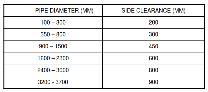
(i) Open-Cut Trenches. The minimum trench width should provide sufficient working room to
adequately place and compact the backfill in the pipe embedment zone. The minimum recommended
width of open cut trenches is shown in the following table.
(ii) Wide Trenches. When the pipe is installed within an embankment, or in installations where the
site is scarified and the pipe is installed within trenches or open cuts formed with general site fill
material the width of compacted backfill must be increased. As a general rule, the pipe zone backfill
material must be compacted for the full width of the trench or two diameters whichever is less.
c. Trench Wall Support
(i) When permanent or temporary trench shoring is used the minimum trench width should be
maintained.
(ii) Sheeting driven into or below the pipe zone that is likely to result in damage to the backfill from
withdrawal should be considered permanent and left in place. Permanent sheeting should be cut off at
least 0.5m above the top of the pipe and be designed to last the life expectancy of the pipe.
(iv) Movable or temporary trench wall supports should not be used below the top of the pipe or within
two pipe diameters from the sides of the pipe unless approved methods are used to maintain the
integrity of the embedment material. Voids left in the embedment material should be filled with backfill
material and adequately compacted.
d. Trench Bottom / Foundation
(i) The trench bottom should be constructed to provide firm, stable and uniform support for the full
length of the pipe. Normally, the trench bottom is considered the top of the pipe foundation when
in-situ soils are stable and uniform. The pipe bedding material is placed on top of any foundation.
(ii) When rock, hardpan or other hard inclusions encountered in the trench bottom it should be
removed and the over-excavation filled with a granular material compacted to provide a suitable
foundation. A cushion should be constructed over any remaining hard inclusions with bedding material
and be at least 300 mm thick. If there is a sudden transition from rock to softer material the possibility
of differential settlement must be considered and accommodated by the cushion. The pipe designer
shall be consulted to provide the requirements for construction of a suitable foundation construction
and cushion.
(iii) When an unstable trench bottom, typically soft, loose, or shows a “quick” tendency, additional
depth should be excavated and a foundation must be constructed to provide firm, stable and uniform
support for the pipe and to minimize differential settlement. In these situations special foundations
may be required. The foundation materials must be selected to avoid migration or the use of a
geotextile fabric shall be considered to prevent the loss of pipe bottom support. The pipe designer
shall be consulted to provide the requirements for construction of a suitable foundation construction.
e. Existing Pipes and Facilities. Installation of pipe in areas where significant differential settlement
is anticipated either from subsidence of underlying soils or from settlement of adjacent structures,
special engineering is required. These are typically uncommon situations and are outside the scope of
this Standard. Interferences with underground structures and with other pipelines are commonly
encountered in the installation of underground pipe and each occurrence should be evaluated on an
individual basis. The following guidelines provide general direction that is consistent or exceed most
manufacturer’s recommendations.
(i) Proximity to Underground Structures
In some instances, the specified lines and grades may place the pipe in close proximity to other
underground structures, within the minimum trench width requirement. In general, the minimum
clearance from foundations and other structures should be 300 mm, measured in any direction from
the pipe. Special care is required for the placement of backfill and compaction in these areas where
accessibility is reduced. If the minimum clearance cannot be maintained, concrete encasement,
cement stabilized sand or other cushioning materials can be used if the potential differential
settlement is considered. In all cases when clearances are less than the minimum trench width the
pipe designer shall be consulted to provide a suitable remedy.
(ii) Proximity to Underground Pipelines
The minimum clearance between the sides of pipes in a multiple pipe installation or vertically
between pipes at cross-overs can be determined using the following formula but shall not be less
than is required to properly place and compact the backfill or the minimum trench width specified for
the largest pipe diameter.
C ≥ (R+ r )/2
—————–
Where:
c = minimum clearance between pipes
R = radius of the first or larger pipe
r = radius of the second or smaller pipe
5.3.5 Pipe Installation
5.3.5.1 Pipe Bedding
a. The pipe bed should be firm and uniform and fully support the pipe along its entire length.
b. The pipe bedding material is placed and compacted on top of the properly prepared pipe
foundation. The pipe bedding material should be the same material utilized for backfilling the pipe in
the initial backfill zone. The minimum thickness of the bedding should be 25 percent of the pipe
diameter or 150 mm whichever is less.
c. The pipe design may require that the bedding be shaped to fit the contour of the pipe. This may
be achieved by loosening 25 to 50 mm of bedding material to achieve a uniform cushion to “seat” the
pipe and placing additional bedding material worked under the pipe and compacted by hand to a
minimum of 5 percent of the pipe diameter.
d. The contractor shall ensure that the requirements of the pipe designer for bedding are achieved
and maintained.
5.3.5.2 Pipe Placement and Joining
a. Pipes with bell and spigot or coupling joints should be assembled in the trench. Pipes with
adhesive bonded or laminated joints can be assembled beside the trench and, after curing and
cooling, lowered into the trench following the manufacturer’s procedures to avoid over-stressing the
pipe.
b. Place pipe and fittings in the trench with the invert conforming to the required elevations, slopes
and alignment. Bell holes should be provided at each joint to ensure that the pipe barrel rests on the
bedding and to facilitate joining. Bell holes should be no larger than necessary to accomplish proper
joint assembly. After joining pipes, assure that bell holes are filled with the appropriate embedment
materials and compacted.
c. Maintain the pipe manufacturers angular joint deflection and pipe bending radius. Do not adjust
the pipe grade by blocking with mounds of soil or other material along the pipe length.
5.3.5.3 Placing and Compacting Backfill
a. Backfill of pipes consists of the initial and final backfill zones as shown in Section 5.3.1 of this
Standard. Proper placement and compaction in the initial backfill zone is important in controlling
deflections and is critical to pipe performance.
b. Take special precautions near bell-and-spigot gasketed joints so as to not cause a significant
difference in the amount of deflection of the spigot versus the bell ends of the pipe. A large difference
in hoop deflection from one side of the joint to the other side may prevent the gaskets from sealing.
This is especially important in larger diameter pipe which are more flexible.
(i)
Initial Backfill Zone. The initial backfill zone extends from the top of the bedding to a minimum of
300 mm above the crown of the pipe. Within this zone only select backfill material is used and should
be the same as that used for the pipe bed.
(ii) Backfill material must be carefully placed and compacted in the haunch areas between the top of
the bedding and the underside of the pipe. This step is critical to ensure that the pipe has proper
support. The material should be pushed into the haunches using a blunt tool and compacted by hand
to achieve full support
(iii) The remainder of the backfill material should be placed in 150 to 300 mm lifts depending on the
material, required compaction density, and compaction method. Between each lift compaction density
should be verified. Care must be taken to avoid excessive compactive effort that may cause bulges,
flat areas, or other local distortions of the pipe wall. Mechanical compaction equipment must not be
allowed to contact the pipe. To avoid contact and inadvertent damage to the pipe and to ensure proper
compaction against the pipe, hand tamping within a 150 mm zone around the pipe should be
considered.
(iv) Final Backfill. The final backfill zone extend from the top of the initial backfill zone to grade. Within
this zone select backfill, common site fill, or in-situ soils. Material choice and compaction depend on
requirements for the final graded surface. The final backfill has little influence on the pipe performance
as long as the unit weight of the material is not greater than the select backfill used in the initial pipe
zone and is well compacted.
(v) The potential for migration from groundwater flow or surface water run off should be evaluated. A
geotextile filter fabric may be required to prevent the migration of fines from the final backfill material
into the select material in the initial backfill zone.
(vi) Compaction Methods. The selection and proper use of compaction equipment shall be
appropriate for the backfill materials used, consistent with installation specification and is the
responsibility of the contractor. Generally, the following guidelines are appropriate for installation of
FRP pipe. Specific requirements are the responsibility of the designer and should meet or exceed the
requirements and limitations of the manufacturer.
(vii) Compaction by hand-tamping should be employed within a 150 mm envelope surrounding the
pipe. This is essential in the haunch areas. Small quantities of soil should be shoveled into place and
thoroughly hand tamped with a tamper suitable for the trench configuration and that will not damage
the pipe.
(viii) Hand operated vibratory plate compactors should not be allowed closer than 150 mm from the
sides of the pipe and until 150 mm of cover above the pipe crown is achieved. Light vibratory-roller
compactors should not be allowed closer than 600 mm from the sides of the pipe and until 600 mm of
cover above the pipe crown is achieved.
5.3.6 Field Monitoring
a. Standard construction practices shall apply to verification of FRP pipe installation for compliance
with installation specifications for trench depth and width, line and grade, trench foundation, bedding
and backfill materials and compaction. Routine inspection during progress of the work shall be
performed to ensure proper installation.
b. Two critical procedures that affect the long-term performance of the pipe are in-place density
testing of the embedment soils and monitoring deflection of the pipe. These procedures shall be
performed in addition to the standard practices.
(i)
In-Place Density Testing. In-place density testing of the pipe foundation, bedding, and backfill
should be made at random locations selected by the contractor. The applicable test method will
depend on the type of soil, moisture content, and the gradation and maximum particle size of the soil.
The contractor is responsible for selection of the appropriate test methods and procedures to verify
that the compaction density required by the design report is achieved.
(ii) Care shall be exercised in the location of the test points to avoid unreliable readings due to
localized interaction between the pipe wall and the compacted soil.
(iii) Density of the foundation, bedding and throughout the full width and depth of each lift of backfill
should be verified.
(iv) The minimum frequency of testing shall be one test every 40 m2
of each lift, with at least one test
each in the bedding and initial backfill zones.
(v) Records of all in-place density testing shall be maintained by the contractor.
c. Pipe Deflection Monitoring
(i) For larger diameter pipes, typically 1200 mm or greater, vertical and horizontal deflections
should be measured within the first 24 hours after completion of backfilling and removal of
de-watering systems. As a minimum, deflections should be measured at the center of each pipe
length, at each joint, and at a maximum spacing along the length of the pipe not exceeding 5 m.
(ii) Bulges, flat areas, or other abrupt changes in pipe wall curvature are not permitted.
(iii) The long-term deflection should not exceed 3 percent of the diameter, which is a design
requirement of SES PO1-E28. To accomplish this, initial deflections should not exceed approximately
2 percent of the pipe diameter. The pipe designer should provide the initial deflection limit as this
requirement is somewhat variable depending upon parameters used in design of the pipe. Pipe
deflection after 30 days should typically not exceed 2.5 percent.
5.3.7 Pipe Buoyancy
Where groundwater or other service conditions indicate the potential for flotation, the pipeline shall be
anchored down as dictated by the designer. The contents of the pipe may not be considered in checking
the resistance of a pipe to flotation. In the absence of detailed analysis, provide cover over the pipe equal
to at least one diameter.
5.3.8 Concrete Encasement
When concrete encasement is called for in the project design, provision will have been made to reduce
stresses at the interface by wrapping the pipe with rubber. The requirements for protecting the pipe at the
interface must be specified by the pipe designer. It is the contractor’s responsibility to provide suitable
foundation support or padding extending from the end of the encasement to mitigate against differential
settlement. Alternatively, flexible joints may be provided at the ends of the encasement. Details of the
encasement including the concrete mix design and any reinforcing shall be provided in the project
documents. No backfill shall be placed until the concrete is cured fully.
5.3.9 Construction Traffic Loading
Pipe systems are often subjected to more severe conditions in construction than in service. Should
construction practices change from those anticipated in design, the contractor must confirm that adequate
protection is provided for the installation. Potential protection measures include:
a. Encasement across high traffic lanes.
b. Using a pipe sleeve.
c. Traffic bearing plates.
d. Alternative support for nearby excavations or structures to minimize temporary loads imposed
on the pipe.
e. Constructing haul roads.
5.3.10 Connections and Appurtenant Structures
This section covers installation requirements and guidance for connecting underground FRP pipe to
various inline and appurtenant structures. In addition to the following requirements, the contractor must
refer to specific installation instructions for components being installed.
a. Thrust Blocks. Where the design calls for thrust blocks, they shall be installed in the dimensions
specified in the design. The concrete shall be reinforced as necessarily to fully transmit the thrust
force to the bearing soils. The following requirements apply to thrust block installation:
(i) Completely surround the pipe for the entire length of the fitting, or a length of at least 300 mm or
one half the diameter, whichever is larger
(ii) At the ends of the encasement the pipe should be wrapped with in rubber to cushion the pipe and
distribute stresses
(iii) Thrust blocks should be shaped with the bearing area against undisturbed native soil or
backfilled with pipe zone material
(iv) The concrete mix shall be accordance with relevant to SES and shall exhibit a minimum strength
as required in the design
(v) Thrust blocks may not be backfilled until the concrete has cured sufficiently to prevent
contamination by the backfill material
(vi)The pipe shall not be tested or placed in service until the concrete has fully cured
b. Pipe Sleeves
When installing pipe in casings or pipe sleeves the pipe should be protected from sliding damage by
using skids attached to the pipe. The pipe designer should provide the material, configuration, and
spacing of skids. The ends of the casing should be closed with a flexible seal to prevent infiltration of
water and soil and to accommodate vertical settlement.
c. Valve Boxes and Manholes
(i)
In line structures may produce local loadings on the pipe. Installation of these structures should
follow project design details precisely. Where the pipe passes through the structure the knockout shall
either be oversized to accommodate 150 percent of the anticipated differential settlement or the pipe
shall be fitted with flexible joints to accommodate the displacement without damage. The knockout
opening shall be sealed water tight.
(ii) Flanged connections at valve boxes should include thermoplastic spacers to ensure proper fit-up,
installation, and servicing of the valve.
6. Field Joining
6.1 General
6.1.1 All field joining methods and procedures shall be in compliance with the manufacturer’s requirements
and the minimum requirements detailed in this Standard. Where conflicts occur, the most stringent
requirement shall be followed.
6.1.2 Pipe and fitting components to be joined by the adhesive bonded or laminated joint methods shall be
restrained from movement until the joints are completed and properly cured. Relative movement of the pipe
to be joined due to thermal expansion and contraction shall be prevented. A combination of mechanical
restraint of the pipe ends to be joined and temporary thermal insulation of the pipe is recommended.
6.1.3 Field joining contractor shall be responsible for the disposal of waste material resulting from field
joining and associated work. Disposal of waste material shall conform with applicable regulations and the
disposal and safety practices of the jobsite.
6.2 Joiner Qualification
6.2.1 Joiner Certification
a. The field joining contractor shall have experience in the joining of FRP piping using the methods
specified for the project and as described in this Standard and shall be able to demonstrate the ability
to perform the required work.
b. Personnel utilized for the field joining of FRP pipe shall be certified in accordance with
SES P14-T02.
6.2.2 Bonding Procedure Specification
a. For each type of adhesive bonded or laminated joint used on the project, field joining contractor
shall prepare a Bonding Procedure Specification (BPS) and implement a procedure which qualifies
the BPS and the performance of each employee (bonder) that will perform the joining of pipe or
fittings on this project.
b. The qualification procedure shall be in accordance with ASME B 31.3, Section A328. The BPS
shall be based on this Standard, the project specification and the pipe manufacturer’s joining
requirements, with additional information provided as required by A328.
c. The qualification testing shall be performed on pipe and fittings representative of that used for
the project.
d. All bonders shall be successfully qualified to these requirements prior to performing joining
operations on the project.
6.3 Adhesive Bonded Joints
6.3.1 Materials
Adhesive materials shall not be used after their documented expiration date. Expired or damaged
materials shall be discarded in an approved manner.
6.3.2 Environmental Controls
a. Materials, pipe and components shall be within the temperature and humidity range
recommended by the manufacturer.
b. Protective enclosures with heating or cooling devices may be required to maintain temperatures
with the required range.
6.3.3 Preparation
a. Check each bonding surface visually for evidence of ultraviolet degradation or other
contamination. Surfaces degraded or contaminated shall be re-surfaced by sanding or other methods
only as approved by the manufacturer.
b. Thoroughly clean and sand all bonding surfaces immediately prior to final joining of the
components. Do not touch or otherwise contaminate bonding surfaces after this preparation is
performed. Surfaces that become wet or otherwise contaminated shall be cleaned, dried and
re-sanded.
6.3.4 Adhesive Mixing
a. Positive methods shall be used to assure proper proportions of adhesive components are used.
b. Mix adhesive components until the mixture has a uniform color and consistency.
c. Once the adhesive mixture begins to produce heat or lumps or gelled masses are evident, the
mixture shall be discarded.
6.3.5 Assembly
a. Before applying adhesive, mark the pipe to identify the proper insertion depth of the spigot into
the bell or coupling.
b. Apply adhesive in a thin uniform layer to the bonding surfaces of both the bell and the spigot. All
machined or sanded surfaces shall be coated with adhesive.
c. Spigots shall be inserted into bells or couplings until they bottom against manufactured pipe
stops or shoulders, or until the reference marks indicate full insertion has occurred.
d. Assembly of the adhesive joint up to the full insertion point shall be performed in a single action to
avoid entrainment of air into the adhesive. If the insertion action is reversed to any extent, the joint
shall be pulled apart, all adhesive removed, and the bonding procedure repeated.
e. Closure of joint may be accomplished by hand methods on smaller diameter pipe, if the proper
insertion depth can be attained. Winch or hydraulic pullers may be required to attain proper insertion
depths, especially on larger diameter pipe. Follow manufacturer’s recommendations at all times to
avoid damage to pipe, components or joints.
f. Ensure that adhesive is not extruded into the bore of the pipe to the extent that a significant
blockage is created. Extruded adhesive shall not exceed the lesser of 10 mm or 5 percent of the pipe
diameter.
6.3.6 Tolerances
a. No visible angular misalignment is permitted.
b. Spigot insertion must achieve the manufacturer’s minimum requirement, as identified by built-in
stops or by reference marks on the exterior of the pipe.
6.3.7 Curing
a.
If required by the manufacturer, adhesive bonded joints shall be heat cured immediately after
assembly.
b. Heat assisted curing shall be performed in a manner that complies with the manufacturer’s
recommendations for temperature and time required for proper curing.
c. Heating collars shall be full wrap type as approved by the manufacturer for use with the specific
joining system being used.
d. Heating collars shall be insulated with accurate temperature control and monitoring. Insulation
shall overlap the heating collar by 100 mm minimum on all sides.
e. Open pipe ends shall be loosely covered with non-sealing devices to prevent interior cooling of
the pipe.
6.4 Laminated Joints
6.4.1Materials
a. Resin
(i) Resin used throughout all laminates shall be the same resin as used in manufacture of the pipe,
or as approved by the pipe manufacturer for use in joining.
(ii) Except as allowed by the manufacturer, no fillers, additives or pigments shall be used in the resin.
A thixotropic agent for viscosity control may be used in accordance with the resin manufacturer’s
recommendations.
(iii) Resin putty shall be made with the same resin used in the laminates and shall contain a minimum
15 percent by weight of milled glass fibers. A fumed-silica additive may be added to increase the
viscosity of the putty.
(iv) Catalysts and promoters shall be a cure system that conforms to the requirements of the resin
manufacturer.
b. Reinforcement
(i) Fiber reinforcement shall have a surface finish and binder that is specifically recommended by
the reinforcement manufacturer for the particular resin system to be used.
(ii) Surfacing veil type and corrosion liner materials shall be the same as used in the manufacture of
the pipe and components, except as allowed by the manufacturer.
(iii) Structural laminate shall consist of mat, woven roving, cloth or other reinforcement materials of
the specific type and weight as specified by the manufacturer for use in laminated joints.
6.4.2 Surface Preparation
a. Surfaces that will receive a laminated joint overlay shall be abraded prior to application of the
overlay, extending a minimum of 25mm beyond the intended edge of the overlay. Abrasion shall be
done by grinding with disks that are new and not contaminated and a grit size of 16 to 24.
b. Abrasion shall remove all traces of glossy resin coat and shall expose the glass fiber over the
entire abraded area. Perimeter of the abraded area shall be smoothly contoured into the surrounding
surface.
c. If abraded area shows any indication of contamination, it shall be cleaned with solvent, the
solvent shall be allowed to evaporate, and abrasion of the area repeated. If application of the
laminated joint overlay does not begin within four hours of surface abrasion, the abrasion shall be
repeated.
d. Dust shall be removed from the abraded area immediately prior to beginning application of the
overlay by vacuuming or brushing with clean nonmetallic brushes or by wiping with clean dry rags.
Dust shall not be removed with solvent or with compressed air.
6.4.3 Environmental Controls
a. Materials shall be stored in a controlled area within the temperature and humidity limits
recommended by the material manufacturers.
b. Except as otherwise allowed by the manufacturer, temperature of materials and laminate surface
during field joining operations shall be maintained within a range of 60 °F to °95 °F and a minimum of
5 °F above dew point.
c. If necessary, field joining contractor shall employ positive methods to assure that environmental
conditions are maintained in the field joining work area. This may require temporary enclosures and
localized heating or cooling.
d. Materials and laminate surfaces shall be protected from dust, fog, rain and other contaminants.
e. If any of the above requirements are exceeded after surface preparation is completed or during
lamination, any affected plies shall be removed. Surface exposed due to the removal of the plies shall
be prepared again before applying new laminate.
f. Contaminated material shall not be used in field joining.
6.4.4 Resin Mixing
a. Resin additives, promotion and catalyst level shall be in accordance with the resin
manufacturer’s recommended limits.
b. Resin shall be promoted and catalyzed such that the working time is adequate to allow proper
application of the joint material in the conditions encountered.
c. Resin shall be tested for gel time and peak exotherm temperature and shall be within the resin
manufacturer’s allowable limits.
6.4.5 Assembly
a. Cut edges of laminates shall be thoroughly coated with resin such that no glass fibers are
exposed.
b. Voids shall be filled with resin putty, allowed to cure, and then ground to a smooth contour.
Ensure that putty is not extruded into the bore of the pipe to the extent that a significant blockage is
created. Extruded putty shall not exceed the lesser of 10 mm or 5 percent of the pipe diameter.
c. Tolerances on gap between cut ends and misalignment of inside surfaces shall not exceed one
third of the thickness of the thinner component.
d. Angular deflection in laminated butt joints shall not exceed 5°, except as detailed otherwise for a
specific joint in the design report. Pipe ends shall be trimmed to accommodate the angle without gaps
or misalignment of the interior surfaces.
6.4.6 Laminate Application
a. Laminate material types and sequences shall conform to the manufacturer’s joining
requirements.
b. Thicknesses specified by the manufacturer are construction minimums. It is the field joining
contractor’s responsibility to assure that minimum thickness is achieved using the specified sequence,
or by adding layers of reinforcement in accordance with the manufacturer’s requirements.
c. Finished laminate surfaces shall be coated with resin that contains sufficient wax to allow full cure
of the surfaces. Final resin coat shall contain UV stabilizer of the type and amount recommended by
the resin manufacturer.
d. Where accessible, an internal joint overlay equivalent to the corrosion liner of the pipe and
components shall be applied to the interior pipe surface at field joint locations.
e. Hand layup structural laminate reinforcement generally consists of mat, woven roving or cloth
plies in accordance with the manufacturer’s joining requirements. Woven roving plies shall have a mat
ply on each side.
f. Edges of woven roving or cloth layers shall be lapped a minimum of 2 in. Lapped edges of
adjacent plies shall be staggered.
g. Abraded area shall be immediately coated with resin using a brush to work the resin into the
surface. Resin coats shall be applied only to the portion of the abraded areas that will be covered
immediately by the laminated joint overlay.
h. Minimum ply width for joint overlays shall be 100 mm. Successive plies shall uniformly increase
in width until the minimum total joint width is achieved. Woven roving plies shall not exceed the width
of adjacent mat plies.
i. Laminated joint overlays shall extend equally within on each side of the joint.
j. Abraded area that is not covered with the overlay shall be coated with waxed resin after
completion of joint overlays.
6.4.7 Exotherm Delays
a. Delays in laminating sequence are necessary in thicker laminates to avoid excessive heat
buildup.
b. If exotherm interruptions are needed, they shall follow application of a mat ply.
c. Joint lamination shall not proceed until the exotherm has completed and the laminate has cooled
to 95 °F or less. Laminate shall not be cooled by artificial means.
d. When lamination is resumed, it shall begin with a mat ply. This may require an additional ply
beyond the number of plies specified.
e.
If interruptions in laminating exceed 24 hours or the laminate surface loses acetone sensitivity or
is contaminated, the surface preparation shall be repeated before laminating resumes.
6.4.8 Curing
a. Field joining contractor shall be responsible for managing the curing characteristics of the resin
so that proper cure and workability are maintained under field conditions. Promotion of resin shall
comply with the resin manufacturer’s recommendations.
b.
If required to achieve proper cure, completed field joints shall be postcured in accordance with
the resin manufacturer’s recommendations.
c. Inspection and all necessary repairs shall be completed and approved by the Purchaser prior to
postcure.
d. Minimum barcol hardness shall be an average reading of 90 percent of the resin manufacturer’s
minimum recommended reading.
6.5 Gasket Sealed Joints
6.5.1 Gasket sealed joints are configured as bell-and-spigot, with either 1 or 2 lip sealing or O-ring gaskets
contained in grooves in either the bell or spigot end. Double bell couplings are also used. If the joint is a
restrained type, a locking strip or other mechanism is incorporated to transfer axial loads across the joint.
6.5.2 The assembly procedure shall be in accordance with the manufacturer’s recommendations and the
following minimum requirements.
a. Bell and spigot ends shall be inspected for damage prior to assembly.
b. Clean all joint surfaces, including the gasket grooves.
c. Verify proper gasket cross-section and diameter.
d. Check non-symmetric gaskets for proper installation in the retaining groove.
e. Apply clean lubricant to gaskets and grooves in accordance with the manufacturer’s
requirements.
f. Assemble joint using approved tooling to assure alignment and avoid damage to the seals.
g. Verify proper insertion length using reference marks if available or other positive means.
h. Use a feeler gauge to verify proper seating of the seals.
i. Verify that all joint tolerances and maximum angular deflection as required by the manufacturer
are satisfied.
j. For restrained joints, insert a clean and lubricated locking strip (if applicable) which extends
around the full joint circumference.
6.6 Flanged Joints
a. Mating Flanges
(i) The typical connection of FRP piping to equipment or pipe of other materials is through the use
of flanges. Flanges shall match the standard drilling patterns used on the project.
(ii) Full faced flanges shall not be mated directly to raised face flanges, ring gaskets, or other
configurations which would cause bending in the FRP flange as bolts are tightened.
(iii) Vanstone style flanges with steel backing rings may be used where rotational adjustment is
desired or for direct mating to raised face or similar flange styles.
b. Alignment
(i) Flanged connections shall be properly aligned with no gaps prior to tightening bolts. Do not force
flanges or other connections into alignment by tightening bolts.
c. Fastener and gasket requirements.
(i) Fastener and gasket material requirements shall be per the standard requirements for the
project.
(ii) Gaskets shall cover the entire face of the flange and be of an appropriate durometer to allow
proper sealing at the design pressure without damage to the flange. Alternately, O-ring gaskets may be used in grooves machined into the flange face, but only when specifically designed by the
manufacturer for this method.
(iii) Fasteners shall be clean and lubricated as needed to attain proper torque.
(iv) Use washers at both nut and bolt heads to protect FRP flanges.
d. Procedure
(i) Tighten bolts in an alternating pattern, using the tightening sequence, torque increments, and
maximum torque as specified by the pipe manufacturer.
(ii) Use a properly calibrated torque wrench in all cases.
(iii) Do not exceed the maximum bolt torques as specified by the FRP pipe manufacturer, or the
manufacturer of the connecting equipment or pipe.
7. Testing
7.1 Soil Testing
7.1.1 Provide testing in accordance with Section 5.3.2, as required to verify that in-situ soil conditions
match the requirements listed in the design report.
7.1.2 Provide in-place density testing in accordance with Section 5.3.6.a as required to verify that the
compaction density required by the design report is achieved.
7.2 Hydrotesting
7.2.1 All joints shall be completely assembled and properly cured prior to filling the system for hydrotesting.
7.2.2 All pipe support saddles shall be properly installed and secured prior to filling or pressurizing the
system.
7.2.3 Underground piping shall be buried to the minimum depth above the top of the pipe as required by
the designer prior to pressurizing the system. All joints shall be left uncovered to allow inspection during the
hydrotest.
7.2.4 Piping system shall be flushed and cleaned prior to filling for hydrotesting.
7.2.5 Hydrotest pressure shall not exceed 150 percent of the design pressure, or the hydrotest pressure as
stated in the design report, whichever is less.
7.2.6 All air shall be vented from the piping system while filling.
7.2.7 High points in the piping system shall be vented while emptying to prevent vacuum.
7.2.8 Test pressure shall be held for a minimum of four hours.
7.2.9 All joints shall be inspected during the hydrotest to detect any leaks.
7.2.10 Additional requirements are included in SES P14-T02, and other SABIC Standards or specifications
as applicable.
7.3 Joint Testing
7.3.1 To the extent possible, gasket sealed joints shall be tested as soon after assembly as practical, in
order to assure seal tightness before continuing with additional installation. If recommended by the
manufacturer, joint testing of underground pipe shall be performed after burial to evaluate the effect of hoop
deflection on the joint.
7.3.2 For gasketed joints using double seals, a fitting may be used which penetrates the space between the
seals. Pressurizing this space will determine if proper sealing has been accomplished. Fitting installation
and pressurization procedure shall be per the manufacturer’s recommendations.
7.3.3 Manufacturers may also have available specialized devices which fit inside the pipe, isolating the joint
and providing a seal against the bore of the pipe. Once a seal is established, vacuum or pressure may be applied to the device to determine if proper sealing of the pipe joint assembly has been accomplished. Use
these devices in accordance with the manufacturer’s instructions.