- GPRS Mobility Management (GMM) procedures: keep track of UE location.
- Attach/detach procedure.
- Routing Area Update (RAU) procedure.
- Session Management (SM) procedures: manage QoS for data session.
- Activate/deactivate/modify PDP Context procedure.
- All previously described procedures require NAS signalling between UE and SGSN.
This article starts with a description of the main UMTS PS procedures. First of all the GPRS Mobility Management (GMM) procedures will be analysed such as the Attach/Detach procedure and the Routing Area Update procedure.
Main goal of these procedures is to keep track of the UE location. Next the Session Management (SM) procedures will be looked at, that manage the Quality of Service for the data session. Most important procedure here is the Activate/deactivate PDP Context procedure. Both GMM and SM procedures require NAS signalling between UE and SGSN.
GPRS Attach Procedure.
- Used to register to PS network: UE known to PS network.
- SGSN checks UE subscription with HLR/VLR.

The GPRS Attach procedure, belonging to the class of GMM procedures, is used to register the UE to the PS network. This way the UE is known to the PS network. The NAS message GPRS Attach Request is sent to the SGSN. This will trigger the SGSN to check the UE subscription with the HLR/VLR. Some optional procedures may be executed regarding authentication and ciphering, and finally the GPRS Attach Accept is sent to the UE.
The UE may reply with the optional uplink message GPRS Attach Complete. This is the message sequence when everything goes ok. In the other case a GPRS Attach Reject may be sent in the downlink to indicate a failed procedure. Reasons could be, for example, illegal UE or GPRS services not allowed. Remark: a message between brackets indicates an optional message.
SGSN.
- Responsible for delivery of data packets to and from UE within its geographical service area.
- Responsible for mobility management.
- Attach/detach procedure.
- Routing Area Update procedure.
- Performs authentication and charging (billing user data) functions.
- Location register contains location information and user profiles of all registered users in its service area.
Main headlines above indicates in more detail the key responsibilities of the SGSN. This network element is responsible for the delivery of PS data packets to and from a UE within its geographical service area. The SGSN also takes care of mobility management (Attach, Routing Area Update), and performs authentication and charging (related to user data) functions. The SGSN contains a location register including information on all registered users in its service area, such as location info and user profiles.
HLR/VLR.
- HLR: contains details on every SIM card issued by the mobile phone operator.
- VLR: temporary database of roaming subscribers.
- Information contained in HLR/VLR:
- IMSl and MSISDN (i.e. telephone number).
- Allowed GM services.
- PS data settings to access packet services.
- Mobility management HLR/VLR:
- Keeps track of Current location of subscriber (e.g. serving SGSN).
- HLR: sends subscriber data to concerned VLR for roaming.
- VLR: contains HLR address of subscriber.
The HLR contains info on every SIM card issued by the mobile phone operator, while the VLR is a temporary database of roaming subscribers. HLR/VLR typically contain info on IMSI and MSISDN, allowed GSM services and PS data settings. HLR/VLR are also involved in mobility management. The HLR forwards subscriber data to the concerned VLR in case of roaming, and the VLR contains the HLR address of the roaming subscriber.
GPRA Detach Procedure (GMM)
In case UE powers down: GPRS Detach Accept not sent by network. GPRS Detach procedure triggers Deactivate PDP Context Procedure.

The GPRS Detach procedure can be initiated both by UE and SGSN. This procedure consists of two NAS messages: GPRS Detach Request, followed by GPRS Detach Accept. This procedure will trigger the Deactivate PDP Context procedure, in case an active PDP Context is still up and running.
Mobility Management.
- Tracking of subscriber location to enable delivery of mobile phone services.
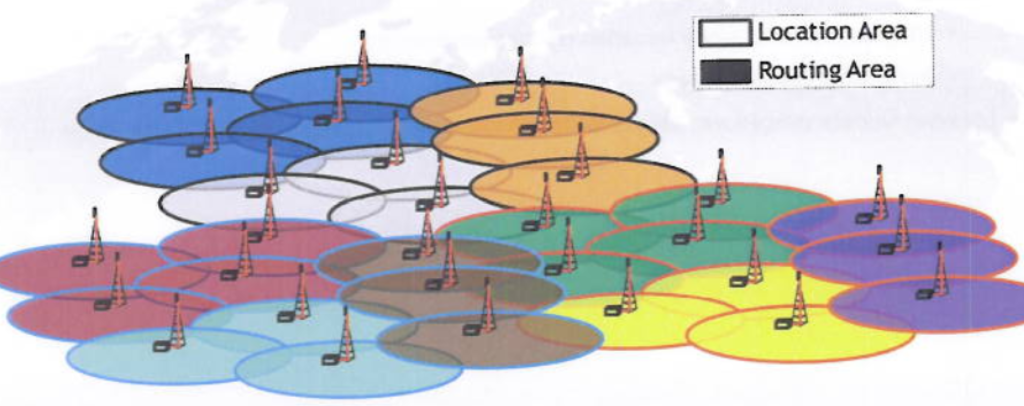
- A group of base stations is called Location Area, or Routing Area.
- Location Area typically consists of multiple Routing Areas.

Tracking of subscriber location is needed to enable delivery of mobile phone services to the user. To make mobility management more efficient, base stations are grouped together in Location Areas and Routing Areas. Location Areas are used for CS services, while Routing areas are defined for PS services. Typically a Location Area contains multiple Routing Areas.
Mobility Management CS – Location Area.
- Set of base stations that are grouped together to optimise signalling.
- Large:
- Many mobiles operating simultaneously.
- Resulting in high paging traffic.
- Small:
- UE must perform many Location Update procedures.
- Resulting in battery drain.
- Location Update procedure: allows UE to inform network about Location Area change.
A location area is a set of base stations grouped together to optimise signalling. This is related to mobility management for CS services. If the Location Area is too big, it will contain many simultaneous operating mobiles, resulting in high paging traffic. A very small Location Area will trigger many Location Update procedures for nomadic users, resulting in unnecessary UE battery drain. This means a balance needs to be achieved regarding Location Area size.
Mobility Management PS – Routing Area.
- PS domain equivalent of location area.
- Used by mobiles which are GPRS-attached.
- Subdivision of location area.
- Bursty nature of packet traffic.
- As a result more paging messages are expected per mobile.
- Advised to reduce paging area.
- Resulting in smaller (compared to Location Area for CS services) Routing Area.
The Routing Area is the PS domain equivalent of the CS Location Area, and is used by mobiles which are GPRS-attached. A Routing Area is a subdivision of a Location Area, in order to further reduce the paging area for PS services. Reason for this is the bursty nature of packet traffic, resulting in more paging messages per mobile, resulting in higher paging load.
Read Also (Part of this Article): Routing Area Update (RAU) Procedure.
Read Also (Part of this Article): PDP Context Activation Procedure.
RRC State Model – Main states.
Two main states:
Idle mode: no RRC connection.
Connected mode: one logical RRC connection.

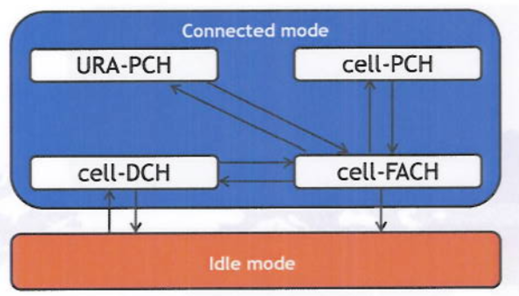
The figure above indicates the two main states in the RRC state model: idle mode and connected mode. In idle mode, no RRC Connection is available. In connected mode however, one RRC Connection is setup.
RRC State Model – Substates.
Connected mode: four substates.
CelL-DCH: UE is allocated dedicated resources (e.g. codes from code tree)
Cell-FACH: UE is using shared resources (common control channels RACH/FACH).
Cell-PCH/URA-PCH:
- UE in sleep mode, not using shared/dedicated resources from network.
- Paging needed to wake up UE, resulting in transition to cell-FACH.
- Location of UE known to network: cell (cell-PCH) Or URA (URA-PCH).

In above picture, one can find the complete RRC state model, including the RRC substates. In connected mode four RRC substates are available: cell-DCH, cell-FACH, cell-PCH and URA-PCH. Arrows indicate the possible transitions between the different RRC (sub)states. In cell-DCH the UE is allocated dedicated resources from the network, such as downlink codes from the code tree.
DCH is the dedicated transport channel used for transport of user data. In cell-FACH the UE is releasing the dedicated resources and falls back to shared resources, such as the common control channels RACH and FACH. In cell-PCH and URA-PCH the UE is in a kind of sleep mode, and is not using any shared or dedicated resources from the network anymore.
To wake up the UE, paging is needed resulting in a transition to cell-FACH. In cell-PCH the UE position is known on cell basis, and a moving UE has to perform cell updates. In URA-PCH the UE location is only known on URA basis, where URA stands for UMTS Routing Area. Typically a Routing Area consists of multiple smaller URAs. The paging area for a UE in URA-PCH is bigger, resulting in less URA updates for a moving user.
RRC state transitions.
RRC state transitions between the following RRC states can be made:
- Idle mode ⇿ cell-DCH: RRC Connection Setup/Release.
- Cell-DCH ⇿ cell-FACH: Radio Bearer Reconfiguration.
- Cell-FACH ⇾ idle mode: RRC Connection Release.
- Celt-FACH ⇿ cell-PCH: Radio Bearer Reconfiguration.
- Cell-FACH ⇿ URA-PCH: Radio Bearer Reconfiguration.
Radio Bearer Reconfiguration contains RRC-State indicator to indicate resulting RRC state.
- Cell-DCH.
- Cell-FACH.
- Cell-PCH.
- URA-PCH.
Typical RRC state transition times:
- Idle mode ⇾ cell-DCH: > 3sec
- Cell-FACH ⇾ cell-DCH: < 1 sec
The above paragraph indicates the different possible RRC state transitions. RRC state transitions can easily be recognised in the log files. Transitions between connected mode and idle mode involve the setup or release of the RRC Connection, using the RRC Connection Setup procedure or the RRC Connection Release procedure.
All other transitions will be performed with a Radio Bearer Reconfiguration message (RRC application protocol). This Radio Bearer Reconfiguration message contains an information element, called RRC-State indicator, indicating the resulting RRC state.
A transition from one state to another one also takes some time. Typically a transition from Idle mode to cell-DCH takes at least 3s, and a transition from cell-FACH to cell DCH takes less than 1s.
RRC state transitions – logfile example.
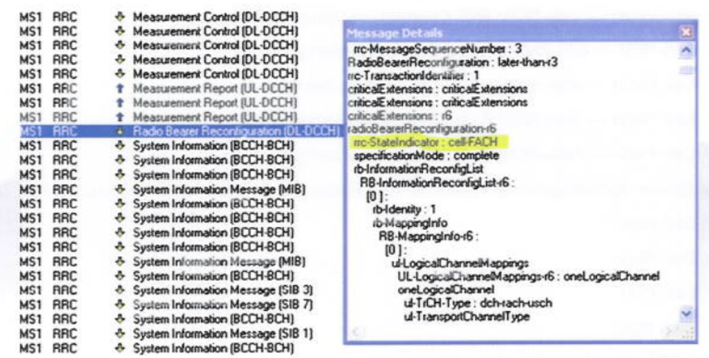
The example below indicates transition from cell-DCH to cell-FACH.

The figure above shows a transition from cell-DCH to cell-FACH, taken from a log file. Before the transition one can recognise the Measurement Report messages in cell-DCH. After the transition with the Radio Bearer Reconfiguration message one can see the system information on the BCCH, which is typical for the cell-FACH state.
When clicking on the Reconfiguration message one can find back the RRC-State lndicator, which is indeed indicating a transition to cell-FACH.
RRC sate transitions inactivity timers.
- Amount of inactivity before transition to lower RRC state is triggered e.g. cell-DCH ⇾ cell-FACH ⇾ cell-PCH ⇾ idle mode.
- Inactivity timer example values:
- Cell-DCH: 5s
- Cell-FACH: 10s
- Cell-PCH: 1hour
- Release of unused resources leads to network capacity gains.
RRC state transitions are often triggered by inactivity timers. Inactivity timers are the amount of inactivity needed before a transition to a lower RRC state is triggered. This can trigger for example transitions from cell-DCH to cell-FACH, from cell-FACH to cell-PCH, and from cell PCH to idle mode.
Above some example values are given for the inactivity timers for different RRC states. The more resources the RRC state is occupying, the shorter the inactivity timer should be. As a consequence the inactivity timer for cell-DCH should be the shortest one. The resulting release of unused resources leads to considerable network capacity gains.
RRC state transitions – inactivity timer scenarios.
- Four different scenarios regarding implemented RRC states and inactivity timers.
- During each of these scenarios, two FTP downloads are performed.
- Total amount of time to perform the two downloads is different for each scenario.

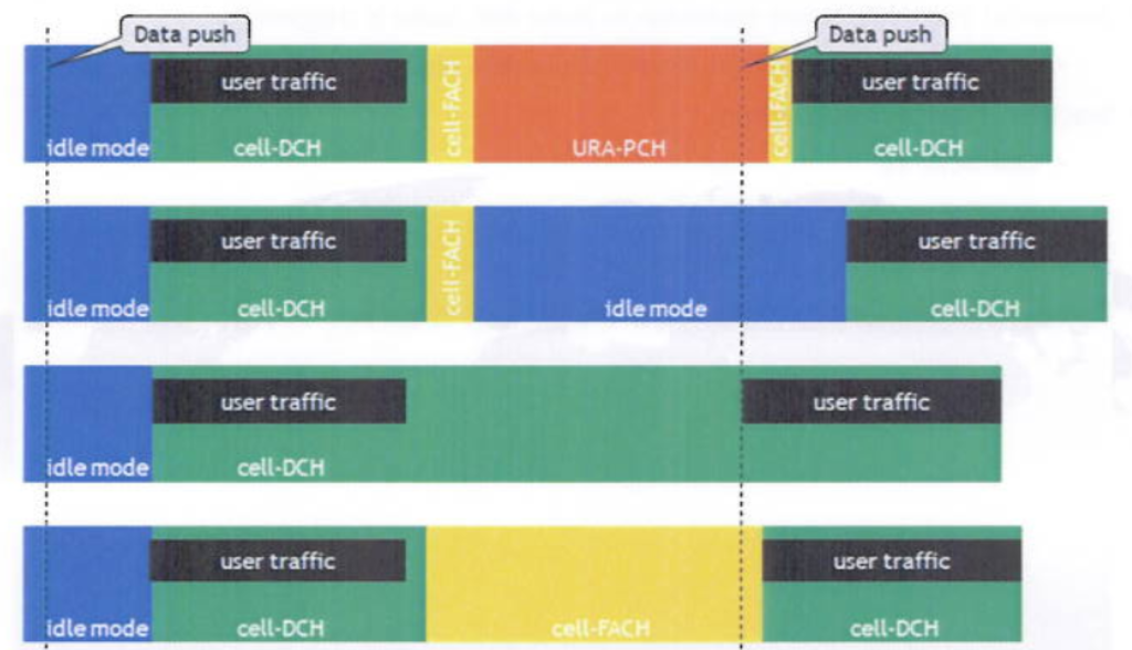
The figure above shows four different scenarios regarding the implemented RRC states and inactivity timers. During each of these scenarios two FTP downloads are performed.
Scenario 1: in this scenario cell-DCH, cell-FACH, URA-PCH and idle mode are implemented. The first download will trigger the transition from idle mode to cell-DCH which takes the longest time. Once the UE is in cell-DCH the actual download (user traffic) can start. Once the first download is finished the UE will stay for some additional time in cell-DCH (cell-DCH inactivity timer) before the dedicated resources are released and the transition to cell-FACH is made. The UE will stay in cell-FACH for the duration cell-FACH inactivity timer before the transition to URA-PCH is triggered. In URA-PCH the UE can stay for quite a long time (e.g. two hours) even when inactive. In the example above the second download is pushing downlink data in the URA-PCH state. The UE will be paged and a transition to cell-FACH will be made. Next the transition to cell-DCH is made and the data transfer can continue. At the end the RRC Connection is released by the user.
Scenario 2: same implementation as scenario 1, but without the URA-PCH state. As a consequence the cell-DCH transition resulting from the second data push will require more time, and the second FTP download will be finished later compared to scenario 1.
Scenario 3: only idle mode and cell-DCH available, and cell-DCH with very long inactivity timer. After the first FTP download, the UE will stay in cell-DCH even when not doing anything for a very long time. When the second data push is coming the dedicated cell-OCH resources are still up and running, and the download can start immediately. This results in the shortest time to complete the two FTP downloads.
Scenario 4: comparable to scenario 2, but with a very long cell-FACH inactivity timer. The second FTP download is pushing in cell-FACH, and the resulting transition to cell-DCH is made quite quickly giving the second best performance of all scenarios.
Event 4a: Transport Channel Traffic Volume (TCTV) above absolute threshold.
- Measurement Report 4a: event 4a must be fulfilled for duration ttt4a.
- Enter event 4a: TCTV » Thld4a
- Leave event 4a: TCTV < Thld4a.
- Trigger transition cell-FACH ⇾ cell-DCH
The above 4 points explains in detail the event 4a, meaning that the Transport Channel Traffic Volume (TCTV) is getting above an absolute threshold. When the TCTV is getting above this threshold, a timer ttt4a is started. If for the duration of this timer this condition is met all the time, the UE will send a Measurement Report 4a in the uplink after timer expiry.
If the TCTV drops again below the absolute threshold Thld4a before timer expiry, the event 4a is not fulfilled anymore and no Measurement Report 4a will be sent. This event is used for UE triggered transition from cell-FACH to cell-DCH, in case the UE has some data to send in the uplink.
Radio Bearer upgrade/downgrade.
- Switching between different data rates.
- 64 kbps – 128kbps – 384kbps
- By changing the uplink/downlink spreading factor.
- Performed with Transport Channel Reconfiguration.
In R99, Radio Bearer upgrades/downgrades between 64kbps, 128kbps and 384kbps are performed with the RRC message Transport Channel Reconfiguration. Data rates are changed by changing the spreading factor in uplink and/or downlink. An overview of the most commonly used spreading factors can be found in the next sections.
Radio Bearer upgrade/downgrade – Spreading Factor.
Symmetrical service: SF DL is double of SF UL.

The table above gives an overview of the different spreading factors available in R99 for uplink and downlink. For a symmetrical service, i.e. a service with the same data rate in uplink and downlink, the spreading factor in the downlink is always the double of the spreading factor in the uplink.
Radio Bearer upgrade/downgrade – logfile example.

The figure above shows some screenshots from a log file. The first Radio Bearer Reconfiguration message indicates a transition from idle mode to connected mode with a downlink data rate of 64kbps (spreading factor 32). The next Transport Channel Reconfiguration is the downlink upgrade from 64kbps to 384kbps, as is indicated with the downlink spreading factor 8.
Inactivity timer tuning.
Balance between user experience, Capacity and UE battery consumption.
- UE battery consumption;
- P(cell-DCH) » P(cell-FACH) > P(cell-PCH) » P(URA-PCH) > P(idle).
- Shorter inactivity timers: quicker transition to lower power consuming RRC state.
- Capacity:
- Cell-DCH: UE is allocated codes from code tree.
- Code availability in DL is limited.
- DL codes should be released asap if not used.
- Shorter inactivity timers: better usage of available capacity.
- User experience:
- Long inactivity timers: all resources stay up and running, even when not used by UE.
- No (or small setup time required for the next download.
- Slow RRC state transition idle mode ⇾ cell-DCH ( 3s) can be avoided.
- Leading to best user experience (smallest waiting time).
Different services would require different optimal inactivity timer settings.
BUT: these settings can not be different for different services.
The inactivity timers have impact on user experience, capacity and UE battery consumption. As is indicated in the slide above cell-DCH is the RRC state with the highest UE battery consumption, followed by cell-FACH, cell-PCH, URA-PCH and idle mode.
This means the shorter the inactivity timers, the quicker the transition is made to a lower power consuming RRC state, and the less the UE battery is drained. In cell-DCH the UE is allocated codes from the code tree, and these downlink dedicated resources are limited. They should be released as soon as possible when not used.
Shorter inactivity timers would result in a better usage of these dedicated resources, and considerable capacity gains would be achieved. With longer inactivity timers all resources stay up and running even when not used by the UE. This leads to shorter setup times (or no setup time at all and best user experience.
Different services result in different average inactivity times (reading times), and this leads to different optimal inactivity timer settings, The only problem is that the inactivity timer settings in the network can not be different for different services.