JUNCTION BOXES AND TEST FACILITIES – CATHODIC PROTECTION
Junction boxes, distribution boxes and test posts
- Junction boxes and distribution boxes shall be installed at suitable levels so as to prevent any ingress of dirt or water.
- Where necessary the supports shall be stabilised in concrete.
- Cables shall run into the boxes through ducting and suitable cable glands.
- When using all-concrete boxes or test posts, the cable ducts may be cast into the concrete. On no account shall cables be clipped direct to, or cast directly into the concrete.
- If junction boxes are supported by pipe, this pipe may be used as cable ducting.
- When test stations are to be installed below grade level (pit type), they shall be provided with a drain facility to drain any (rain) water.
- Junction boxes, distribution boxes and test posts shall be provided with cable terminals, bolted to an insulated panel or insulated “Klippon” type cable terminals suitable for the number and size of cables to be installed. The box shall provide ample room to terminate the cable ends without excessive bending of cables and without the cables exerting stress on the cable terminals.
- When installing current control devices such as resistors and diodes, sufficient ventilation or heat sinks shall be provided to avoid a temperature rise of more than 10 °C above ambient temperature.
- All test terminals and shunts shall be accessible upon opening the door of the distribution box or test post. Test posts may be provided with contact terminals at the outside of the box for quick access. Such terminals shall be made of corrosion resistant materials (e.g. brass or stainless steel) and shall be fully isolated from the box, also when concrete boxes are used.
- For cable installation see CABLE INSTALLATION OF CATHODIC PROTECTION.
Cathodic Protection Test Facilities
The following test facilities shall be installed at the locations.
The cables to each pipeline or structure shall be identified by colour coding or tags. Recommended colour coding is given in the diagrams.
Make sure there is sufficient slack in the cables to allow for subsidence without putting any stress on the “cable-to-structure” connection.
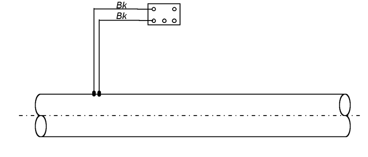
Potential monitoring station
A standard potential monitoring station shall have two separate cables attached to the pipeline and terminated in the test post.
Standard potential test station
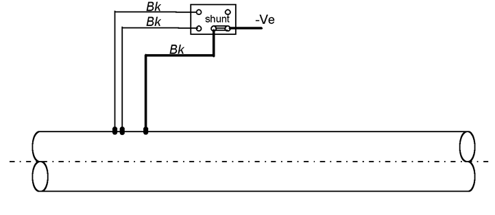
Drain point control facilities (at CP Stations)
At the drain points, each negative connection to the pipeline shall be provided with current measuring facilities. For single pipelines the ammeter built into the current source may suffice. Where multiple negative connections are installed separate shunts and blocking diodes shall be provided, installed in a distribution box.
At the drain point a potential monitoring station shall be installed using a separate test cable connected to the pipeline for the measurement of the drain point potential.
Drainpoint / potential test station
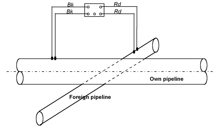
Foreign pipeline bonding station
At crossings with foreign pipelines, a bonding facility shall be provided, consisting of two separate cables attached to each individual pipeline, terminated in a test post with suitable facilities to install direct or resistive bonds. The cables to each pipeline shall be identified by colour coding or tags.
Potential test station at pipeline crossing
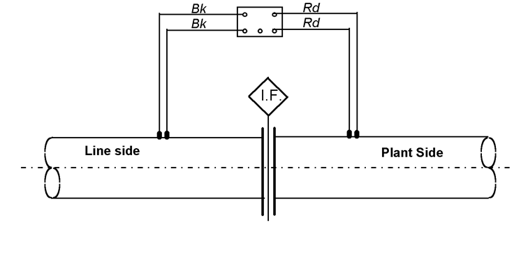
Test facilities at isolating joints/flanges
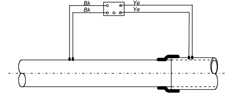
At all isolating joints/flanges, two cables shall be connected to each side of the joint or flange. All cables shall be separately terminated in one test post with suitable facilities to install direct or resistive bonds.
Test station at isolating flange / joint
Test facilities at casings ( road/railway crossings)
Test facilities shall be installed at both ends of the casing, but on casings shorter than 10 m the test facility shall be installed at one end only.
In each test facility, two test cables shall be connected to the pipeline and, if steel casing is used, see Figure, two test cables shall be connected to the casing. All cables shall be terminated in one test post.
Test station at steel casing
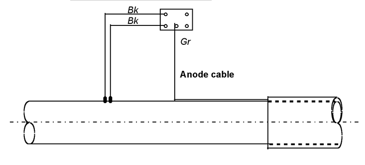
When a non-metal, or externally coated metal casing is used and a sacrificial anode is installed inside the casing, the anode cable tail shall be terminated inside the test post where the anode-to-pipeline connection can be made (see Figure).
Test station at non-metal casing
Ribbon anodes are best installed inside slotted PVC pipes to avoid electrical contact with the casing and to enable replacement when required.
Sacrificial anode connection
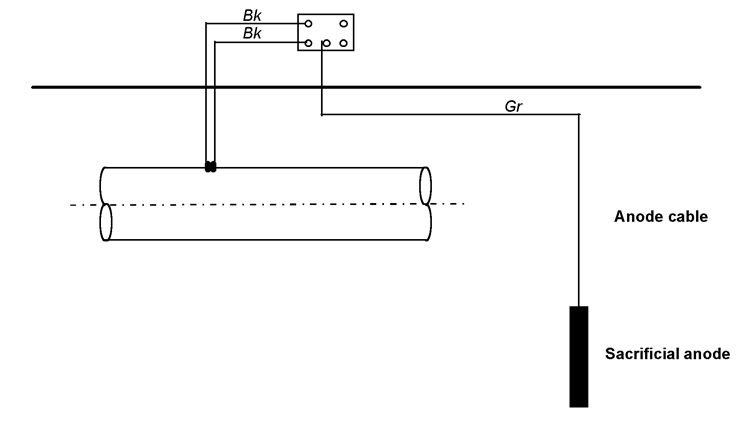
Where underground sacrificial anodes are installed, two cables shall be connected to the pipeline or structure and, together with the anode cable tail(s), terminated in a test post with facilities to install direct or resistive bonds (see Figure ).
Sacrificial anode connection
Line current test stations
Where required by the design, line current test stations shall be installed consisting of two sets of two cables connected to the pipeline at about 100 metres distance from each other and terminated in one test post (see Figure ). The cables connected in the remote location shall be strapped to the pipe (new pipeline construction) or buried at sufficient depth close to the pipeline.
Line current / potential test station
Permanent reference electrodes
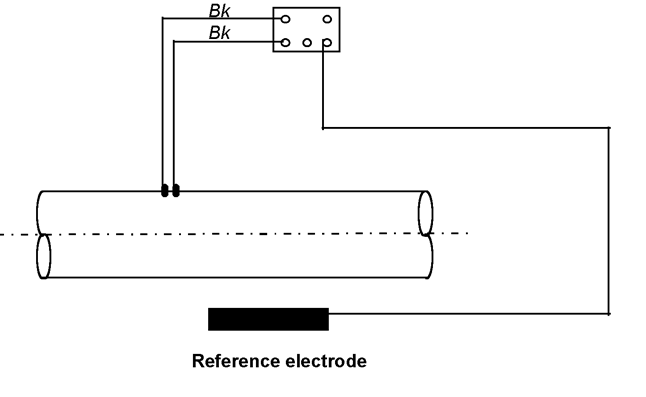
Permanent reference electrodes may be installed on pipelines, under vertical tanks (see Figure ) and buried or mounded vessels, on underwater on offshore pipelines and structures.
Permanent reference electrode
Before installation, permanent reference electrodes shall be inspected for the correct type and for any damage to the electrode or cable. Damaged cables shall not be used. Sufficient cable length shall be provided for installation without underwater or underground splices. Before installation the electrode shall be calibrated against a standard reference electrode while immersed in water or wet soil in accordance with the Manufacturer’s instructions. The location shall be checked to comply with the design. The electrode shall normally be installed close to the pipeline or structure in accordance with the Manufacturer’s instructions or the design drawings. Cable tails shall be identified by tags. After installation the cables and the electrodes shall be protected from any damage due to ongoing construction work.
Where permanent reference electrodes are installed, a permanent (test) cable connection to the pipeline/structure shall be made, which shall be separate from the negative current connection (drain cable). Underground cables shall be installed in accordance with (CABLE INSTALLATION OF CATHODIC PROTECTION). Underwater cables shall be installed similar to under water anode cables (CABLE INSTALLATION OF CATHODIC PROTECTION). The electrode cable tails and the test cable to the structure shall be terminated in a junction box.
Monitoring facilities on offshore Structures
On offshore structures, monitoring points shall be located so that all critical members will be monitored. The selection of locations shall be such that about 10% of the typical members, such as jetty piles, are covered.
At the elected monitoring stations, permanent connection points to the structure shall be installed. These may consist of a cable, connected to the structure and terminated in an accessible place, or a dedicated corrosion-free stud or earthing boss welded to the structure. The dimensions of the terminals shall be such that a standard size cable clip can be attached to it. The locations of the test stations shall be selected to provide safe access to the structure’s edge where the reference cell is to be lowered into the water.
Where permanent reference electrodes are installed, both the reference cable(s) and the structure connection are to be terminated in one junction box.
All test stations shall be marked using a permanent identification and their location and identification code shall be recorded.
