This article is about Liquid Tight Flexible Metal Conduit LT Flex Material Selection Guide & Technical Specification for commercial buildings, plants and refinery projects as per international codes and standards. LFMC and associated fittings shall be listed as meeting the requirements of UL 360.
[NFPA 70, NEC 350.6]
Liquid Tight Flexible Metal Conduit LT Flex Material Technical Requirements
| Minimum Size: LFMC smaller than metric designator 16 (trade size 1⁄2) shall not be used. Exception: LFMC of metric designator 12 (trade size 3⁄8) shall be permitted as covered in 348.20(A). [NFPA 70, NEC 350.20 (A)] |
| Maximum Size: The maximum size of LFMC shall be metric designator 103 (trade size 4). FPN: See 300.1(C) for the metric designators and trade sizes. These are for identification purposes only and do not relate to actual dimensions. (See Attachment 1) [NFPA 70, NEC 350.20 (B)] |
| Marking: LFMC shall be marked according to 110.21. The trade size and other information required by the listing shall also be marked on the conduit. Conduit suitable for direct burial shall be so marked. [NFPA 70, NEC 350.120] |
| Conduit in trade sizes 3/8 – 1-1/4 (12 – 35) shall be provided with a bonding strip wound enclosed by the conduit convolutions throughout the entire length of the conduit. [UL 360 Sec. 3.1] |
Jacket Thickness: The thickness of the finished jacket shall not be less than indicated in Table 4.1 (Attachment 2) when determined as
described below:
The minimum average thickness of the jacket is to be determined by measuring a specimen of the jacket removed from the finished conduit and buffed to remove any ridges or other irregularities on the inside surface of the jacket. The specimen is to be selected to include the thinnest portion of the jacket as determined visually. Measurements are to be made with a dead-weight dial micrometer having a presser foot 0.250 ±0.010 inch (6.4 ±0.2 mm) in diameter and exerting a total of 3.0 ±0.1 ozf (0.84 ±0.02 N or 85 ±3 gf) on the specimen – the load being applied by means of a weight. Five readings are to be taken at different points on the specimen and the average taken as the minimum acceptable average thickness, or by means of an optical device accurate to at least 0.001 inch (0.01 mm).
[UL 360 Sec. 4.1]
Conduit Diameters: Finished steel conduit shall not be larger or smaller in internal and external diameter than indicated in Table 5.1 (Attachment 3) when determined as described below:
Compliance of all trade sizes of conduit with the minimum and maximum internal diameters in Table 5.1 is to be determined by means of a vernier caliper accurate to at least 0.001 inch (0.01 mm).
[UL 360 Sec. 5.1]
| Corrosion Protection: The corrosion protection of the steel strip from which the conduit is formed shall comply with the requirements of the Zinc-Coating Test, Section 14. A coating of zinc is not required on the cut edges. [UL 360 Sec. 6.1] |
| New and Unused – Electrical materials shall be new and unused. |
| As Designed – Electrical materials shall be in accordance with the Saudi Aramco-approved project-specific design drawings, diagrams, schedules, lists, databases, and associated documents (in particular, raceway type and trade size as shown on electrical BOM and raceway schedules). |
| Free of Damage – Electrical materials shall be free of damage. |
| QC Before Installation – Electrical materials shall conform to all applicable requirements, standards, and specifications prior to release to be used as part of the work. |
| Identification – Electrical materials shall be identified by using tags, stamps, color coding, stencils or labels. The location and method of identification shall not affect the function or quality of the materials. |
| Traceability – Electrical materials shall be traceable from the manufacturer and supplier through delivery, storage, fabrication, erection, installation, repair, modification and use. |
| MARKINGS: All markings shall be clearly legible. Markings that are in addition to the surface legend and other markings required in this standard are acceptable if the additional markings do not conflict with and cannot be confused with the required markings. [UL 360 Sec. 23.1] |
| MARKINGS: The surface markings required in 23.4 shall appear throughout the length of every piece of the conduit that is made and shall be repeated at intervals that are not longer than 24 inches (610 mm). [UL 360 Sec. 23.3] |
MARKINGS: The outside surface of every length of liquid-tight flexible steel conduit produced shall be marked with each of the following:
a) The trade size of the conduit from 1.1.
b) The name or trademark of the conduit manufacturer, that manufacturer’s trade name for the conduit, both, or any other distinctive marking by means of which the organization that is responsible for the conduit can readily be identified.
c) A distinctive identification of the factory if the organization that is
responsible for the conduit operates more than one factory in which
liquid-tight flexible steel conduit is made. The factory identification
may be in code, the meaning of which shall be made available.
[UL 360 Sec. 23.4]
The statement “Use separate grounding conductor on circuits rated over 20 A” shall be durably and legibly marked at intervals no longer than 24 inches (610 mm) on the outer surface of the jacket on every length of finished conduit in the 3/8 (12) and 1/2 (16) trade sizes. The same statement with “60 A” in place of “20 A” shall likewise be marked on finished conduit in the 3/4 (21), 1 (27), and 1-1/4 (35) trade sizes.
The acceptable means of achieving this marking are indicated below (Item B18). [UL 360 Sec. 23.5]
Embossed (raised) lettering is acceptable. Ink printing is acceptable if it complies with the durability requirements in 22.1 – 22.5. Indent printing is acceptable if the thickness of the jacket is not reduced below the value shown in Table 4.1 (Attachment 2). [UL 360 Sec. 23.6]
International Codes & Standards
| 1. NFPA 70 – National Electrical Code, (NEC) 2008 Edition |
| 2. UL 360 – Standard for Liquid-Tight Flexible Steel Conduit. |
| 3. SAES-P-104 – Wiring methods and Materials. |
| 4. SAES-P-100 – Basic Power System Design Criteria. |
Table 300.1 – Metric Designators and Trade Sizes – NFPA 70
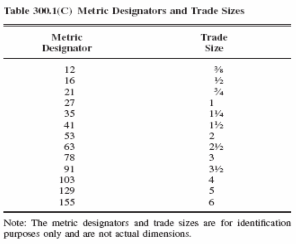
Table 4.1 – Jacket Thickness – UL 360
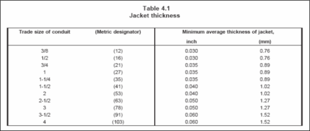
Table 5.1 – Internal and External Diameters – UL 360
