Following topics to be discussed in this article are
1. SCOPE
2. REFERENCES
3. GENERAL
3.1 Lateral Support
3.2 Code Requirements
4. REVISION HISTORY
FIGURE 1 – Plan View, Vertical Supports
FIGURE 2 – Sectional Views, Horizontal Supports
FIGURE 2A. Between Floors, Floor and Roof
FIGURE 2B. Between Floor and Roof
TABLE I – Horizontal or Vertical Supports, Dimensional Limitations
1. Scope
1.1 This procedure is a guide when used in conjunction with applicable building codes for determining dimensional limitations of exterior load-bearing masonry (concrete hollow block) walls.
1.2 This article is not applicable to firewalls and fire partitions.
2. Standards and Codes References
Reference is made in this standard to the following documents.
American Concrete Institute (ACI)
530 Building Code Requirements for Masonry Structures and Commentary
American Society for Testing and Materials (ASTM)
C 90 Standard Specification for Hollow Load-Bearing Masonry Units
C 270 Standard Specification for Mortar for Unit Masonry
International Conference of Building Officials (ICBO)
Uniform Building Code (UBC) 1997
National Concrete Masonry Association (NCMA) of U.S.A.
Non-reinforced Concrete Masonry Design Tables
3. General
The masonry units (concrete hollow blocks for load bearing walls) shall conform to SASO SSA 145 and ASTM C 90 and shall be as specified in SES A03-S01. The mortar for masonry shall conform to ASTM C 270, Type N or S.
3.1 Lateral Support
Required lateral support should be either horizontal or vertical but not necessarily in both directions. Maximum ratio of unsupported length (L) or height (H) to nominal thickness (T) for walls of hollow concrete block is 18. See Figure 1 and Table I.
3.2 Code Requirements
The ICBO uniform building code (UBC) 1997 requirements for masonry structures, and ACI 530 shall be used for the structural design and construction of masonry walls.
FIGURE 1 –Plan View, Vertical Supports (See Table I)
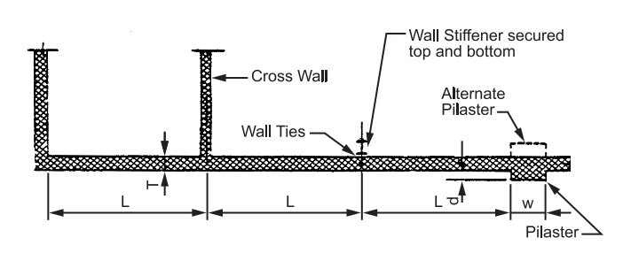
FIGURE 2 – Sectional Views, Horizontal Supports (See Table I)

TABLE I – Horizontal or Vertical Supports, Dimensional Limitations

Notes:
(1) Consult ACI and applicable standards for allowable stresses and maximum-length or height to thickness ratios.
(2) This standard applies to uniformly distributed loads only.
(3) Concentrated loads on the walls will require properly designed bearing details to adequately distribute the load into the wall.
(4) This standard does not consider excessive horizontal loads, for example hurricane winds and blasts or excessive vertical loads. These require special consideration and design.
(5) For masonry wall anchorage see Commentary on ACI 530, Chapter 1.
(6) For expansion and control joint spacing, see SES A03-E01.
(7) For additional information see Nonreinforced Concrete Masonry Design Tables by National Concrete Masonry Association.
(8) For cavity walls, provide minimum 4 ties/m².