This article is about Low-Voltage Wiring Installation method statement and technical specification for engineers.
What is Low Voltage Wiring?
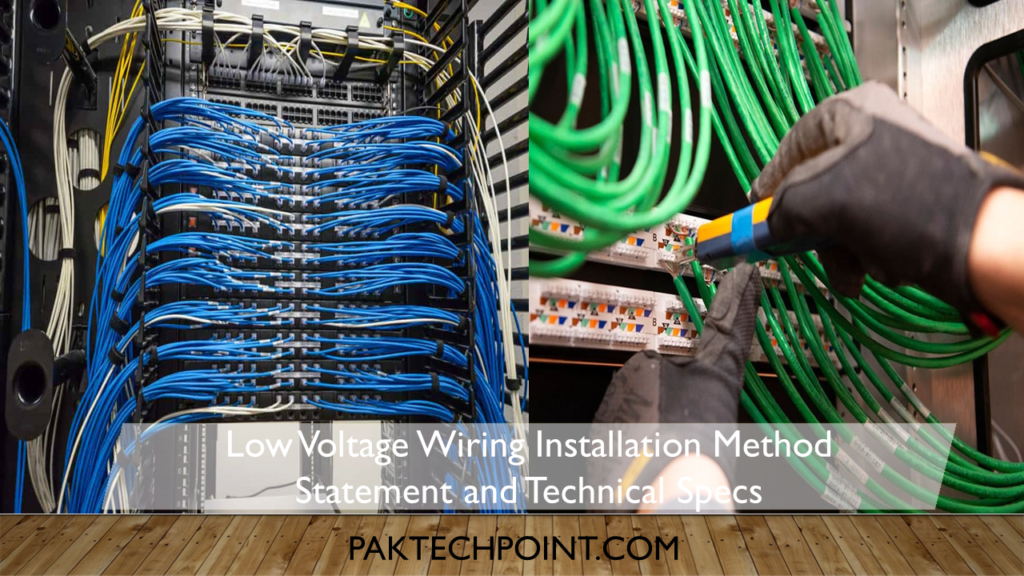
Low-voltage wiring primarily consists of shielded instrument and thermocouple wire. When working with such wiring, it is essential to adhere to specific guidelines to ensure proper installation and prevent unwanted grounding or interference. The procedures to be followed include:
1. Shielded Wire Handling
The overall and individual shields should only be stripped back to the extent necessary for installation, and their ends should be securely fastened using tape or heat-shrink tubing. Overall shield drain wires must be grounded at a single point, typically the programmable electronic system (PES) equipment’s safety ground bus or the control panel safety ground bus. If the multi-cable does not reach the PES or control panel, the overall shield drain wires should be grounded at the nearest terminal box electrically connected to the PES or control panel.
In terminal boxes, control panels, and PES cabinets, the outer jacket of single-pair cables and single-triad cables should only be stripped back as needed for installation, usually between the cable tag and the termination point. When wireways are used for routing wiring, only the section of the cable extending beyond the wireway, between the cable tag and the termination point, should be stripped back to the necessary extent for installation.
All terminated shield drain wires should be covered with clear heat-shrink sleeving along their entire exposed length. This prevents accidental contact with grounded surfaces or exposed conductor portions. Cable shielding should not be stripped, exposing shields, until the actual termination of cable conductors is performed. This is especially crucial when electronic system testing is conducted before the complete termination of all system wiring.
The ground wire from the plant’s grounding electrode system, individual shield connections to grounded instruments, and overall shield/drain wire connections must be terminated before energizing the power to the PES or control panel.
The Engineering contractor or installer is responsible for reporting to the Plant owner field representative any shield drain wire that is not grounded or is grounded at more than one point.
Commonly uses grounded thermocouples. Consequently, all thermocouple conductors should be installed, terminated, and checked for spurious grounding before final connection to the grounded field element.
In thermocouple heads, the contractor should strip back only the shield and drain wire, leaving room for a small service loop. The shield should be secured with heat shrink or tape, and the drain wire should be connected to the grounding screw. Since the drain wire has been connected at this field device, the contractor must ensure that the other end of this drain wire has not been tied to ground, cut back, and insulate the shield and drain wire.
Wiring to control panel terminal strips should be installed in a manner that allows all wire markers to remain visible without requiring the removal of wiring duct covers.
2. Continuity Check
All thermocouple and instrument wiring must undergo continuity checks and point-to-point terminations to verify proper connections.
3. Termination of Thermocouple and Instrument Wire
Thermocouple and instrument wires should be terminated as follows:
| Device | Device Marking | Wire Color |
| ISA Type T Thermocouple | + Blue | – Red |
| ISA Type J Thermocouple | + White | – Red |
| ISA Type K Thermocouple | + Yellow | – Red |
| Resistance | Red (Black) | Red |
| Temperature | White (Yellow) | White |
| Detectors (RTDs) | Red (Black) | Black |
| Instruments (mV and mA) | + Black | – White |
| Bentley Nevada | -18 Vdc | Red |
| Proximitors | Common Output | Black, White |
4. Wiring for Low Voltage Instruments
When installing low-voltage wiring for instrumentation, ensure that there is a service loop in cable or wiring runs inside junction boxes, control panels, and instrumentation termination heads. This extra wire allows for ease of service, replacement, or retrofit activities in the future.