In LTE networks, which are primarily designed for data services, traffic is a key performance indicator (KPI) that reflects network performance. The main goals of LTE network improvement include achieving faster data rates (throughput), reducing latency, lowering costs, and increasing system capacity and coverage.
During the optimization phase of an LTE network, several common issues need to be addressed:
- Weak Coverage: Areas with insufficient signal strength that affect service quality.
- Low SINR (Signal-to-Interference-plus-Noise Ratio): Poor signal quality due to interference or noise, leading to degraded network performance.
- Inter-Frequency Interference: Interference between different frequency bands that can disrupt communication.
- Intra-Frequency Interference: Interference within the same frequency band, which can cause issues in maintaining stable connections.
Solving these problems is crucial for maintaining and improving LTE cell throughput.
LTE Throughput Analysis Methods.
To analyze throughput / Data rate downloading problems in an LTE network, follow this structured workflow:
- Check for Alarms: Start by verifying if any alarms have been reported at the fault site. Alarms can provide initial clues about potential issues.
- Assess Interference and Coverage: Investigate whether there is interference or weak coverage in the area, as these are common causes of traffic problems.
- Review Engineering Parameters and Transmission: Examine the engineering parameters and transmission settings to identify any configuration issues.
- Document and Report: Write a detailed problem description, including the check results. Then, forward this problem report to R&D engineers for further analysis and resolution.

Analysis of the Cell with the Maximum Throughput Rate Less than 5Mb.
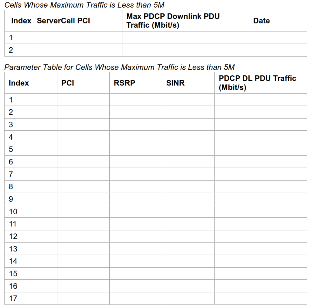
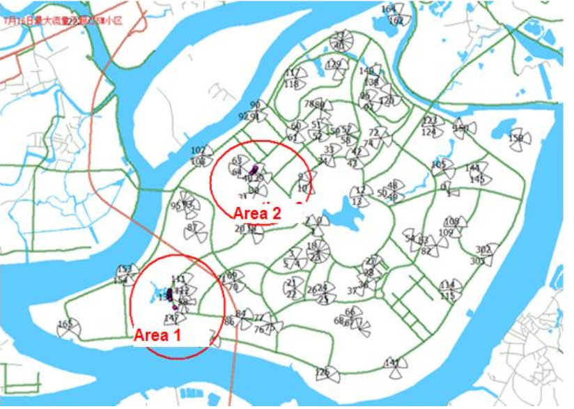
First export traffic data from the DT test data, and filter out all cells whose maximum traffic is less than 5M.
Area 1 Analysis.

Problem
During a handover from cell PCI149 to cell PCI134, the UE sends a measurement report but does not receive any response. Consequently, it triggers an RRC connection re-establishment in the target handover cell, which is refused, leading to the initiation of a new service re-establishment.
Problem Analysis
Upon examining the neighboring cell configuration, no misconfiguration was found. However, cells PCI147 and PCI149 were identified as causing pilot frequency pollution in area 1. This interference resulted in low SINR, handover failures, and a reduced bitrate.
Solution
To address the issue, the power of cells PCI147 and PCI149 was reduced from 12 to 9, while the power of cell PCI134 was increased from 9 to 12.
Verification Test Results
Post-adjustment, the UE successfully performed handovers between cell PCI 86, PCI 134, PCI 133, and PCI 113 as it moved through the area. Cells PCI147 and PCI149 no longer impacted the coverage in this region, SINR improved to 10dB, and both handover and data rates returned to normal.
Area 2 Analysis.
Problem:
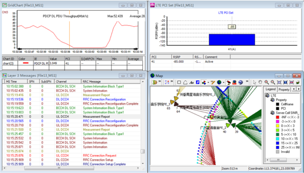
In the scenario shown, when the UE moves through area 2, it experiences handovers between cell PCI32, PCI64, and PCI4. A ping-pong handover occurs frequently between cells PCI41 and PCI64, resulting in call drops, service re-establishment, and reduced data rates.
Problem Analysis:
Cell PCI64 covers a campus area with a small coverage radius. As the UE moves between cells PCI41 and PCI64, the signal from cell PCI64 weakens quickly, causing low SINR, call drops, and a lack of service traffic.
Solution:
To resolve the ping-pong handover issue, it is necessary to reduce cell PCI64’s coverage in the problematic area. This can be achieved by lowering the antenna’s tilt by 3 degrees or reducing the RS power in cell PCI64.
Verification Test Results:
After the adjustment, the ping-pong handover and call drop issues were resolved, and traffic returned to normal levels.
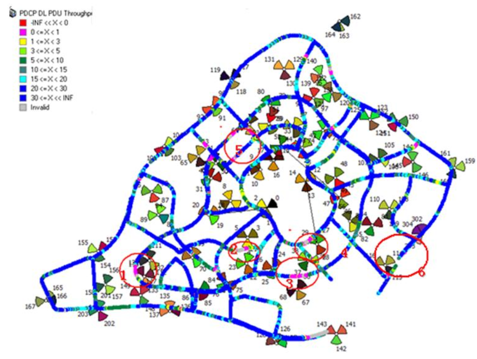
Analysis the Cell with the Average Throughput Rate Ranging from 5Mb to 10Mb.

Area 2 Analysis.
Problem
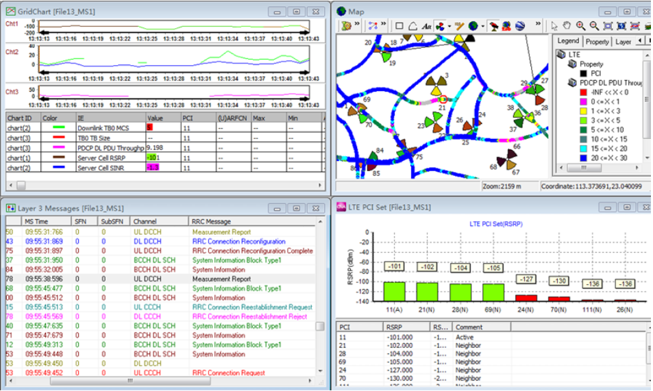
When the UE conducts a handover between cell PCI11 and cell PCI21, it sends out a measurement report, but the eNodeB either does not receive this report, or the UE does not receive the handover judgment sent by the eNodeB. This results in handover failure, service re-establishment issues, and a low data rate.
Problem Analysis
Area 2 is covered by multiple cells, including PCI11, PCI21, PCI28, and PCI69, with an RSRP of about -101dB. The cell PCI11 is approximately one kilometer away from this area, leading to signal overshoot. Additionally, cells PCI11 and PCI21 are not configured as neighboring cells. Consequently, when the UE moves through cell PCI11, it cannot receive the handover judgment for transitioning to cell PCI21, even after sending the measurement report.
Solution
To address this issue, you can either lower the tilt of the antenna in cell PCI11 to reduce signal overshoot, or configure a neighboring cell relationship between cell PCI11 and cell PCI21 to ensure proper handover judgment and execution.
Area 3 Analysis.
Problem
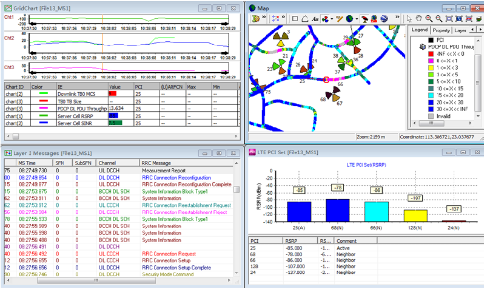
When the UE is making phone calls or using data services in cell PCI25, it detects a strong RSRP signal from cell PCI68, which triggers a handover from PCI25 to PCI68. However, the handover fails, the service re-establishment is refused, and no traffic is detected in the area for a certain period.
Problem Analysis
After the UE receives the handover judgment from the eNodeB, it sends back the Handover Reconfiguration Completion message. However, the RS power in cell PCI68 suddenly disappears, leading to handover failure. This issue may be caused by a breakdown or malfunction in cell PCI68.
Solution
To resolve this issue, troubleshoot the problem in cell PCI68 to identify and rectify the underlying cause of the power disappearance and handover failure.
Area 4 Analysis.
Problem:
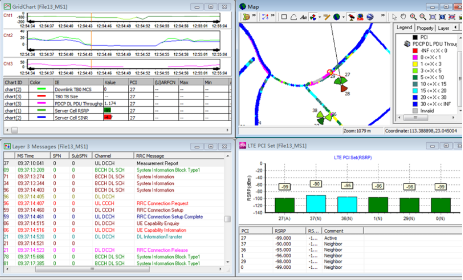
When the UE attempts to handover from PCI27 to PCI39, the handover fails, leading to call drops, service re-establishments, and low data rates in the area.
Problem Analysis
The issue stems from the fact that cell PCI29, which covers the Information Building 3, has its antenna installed in the center of the building’s roof. This placement results in weak coverage in the surrounding area, causing handover failures and degraded service quality.
Solution:
To resolve the issue, configure a neighbor cell relationship between cell PCI27 and cell PCI37. This adjustment will help ensure smoother handovers and improve coverage, reducing the likelihood of call drops and service interruptions.
Area 5 Analysis.
Problem
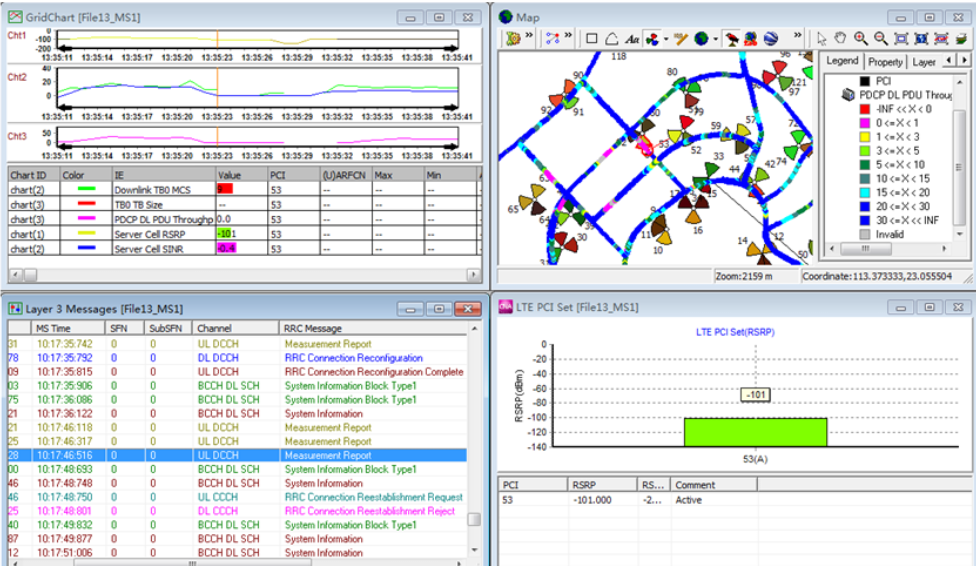
When the UE moves from cell PCI53 to PCI61, it sends numerous handover requests to the eNodeB but does not receive any handover decision. This leads to handover failures.
Problem Analysis
The issue arises due to the presence of residential buildings and a high-rise crossroad between cell PCI53 and PCI61, particularly in area 5. These obstacles cause the signal from PCI53 to weaken rapidly at the turning corner, resulting in handover failures.
Solution
To address this issue:
- Lower the RS power of cell PCI53 from 12 dBm to 9 dBm. This reduces the signal strength of PCI53, making the handover to PCI61 more likely.
- Raise the RS power of cell PCI61 from 6 dBm to 9 dBm to improve its coverage and signal strength in the affected area.
- Increase the neighboring cell offset by 3 dB to make the UE more likely to select PCI61 for handover.
Verification Test Results
After implementing these adjustments, the handover process in area 5 was restored to normal, and the data rate improved, resolving the issue.