Magnetization Circular Fields
A circular magnetic field is induced into a test object either by
passing magnetizing current directly through the test object (direct
magnetization), or by passing current through a conductor
surrounded by the test object (indirect magnetization). In direct
magnetization, the magnetic field will be uniform throughout the
length of the test object if the test object is uniform in all respects.
Direct induction of a circular field is accomplished by passing a
short pulse of current through the test object, as shown in
Figure 3.la. The test object is placed between two heads on a bench
unit. This is called a head shot.
Another direct method of inducing a circular field is by the use of
prods, shown in Figure b. Prod magnetization is used where the
size or location of the test object does not permit the use of a head
shot or central conductor. Current flow and field distribution are also
shown in Figure. The field between the prods is somewhat
distorted by the interaction of the two fields. Prod magnetization is
most effective when the prods are spaced 15 to 20 cm (6 to 8 in.)
apart.
Circular magnetization by direct and indirect
current induction: (a) head shot; (b) prods; and (c) central
conductor.

With indirect induction of a circular field, the object to be
magnetized is placed so that a current carrying conductor induces a
magnetic field into the test object. This method is called the central
conductor method, and is illustrated in Figure 3.lc. The use of a
central conductor also eliminates the possibility of a test object
being burned by the flow of excess current or if poor contact is
made with the heads.
Circular magnetic fields induced directly by the passage of
alternating current can produce very high surface sensitivities caused
by the so-called skin effect, where the current is transmitted on the
surface of the test object.
When current passes through a conductor, a magnetic field is
formed in and around the conductor. If the conductor has a uniform
shape (a copper rod), the density of the external field is uniform at
the same radial point along the length of the conductor. At any point
on the conductor, the magnetic field is strongest at the surface of the
conductor and decreases as the distance from the conductor
increases. Direction of the magnetic field (lines of force) is at a 90
degree angle to that of the current in the conductor.
The right hand rule, shown in Figure, is an easy method for
determining the direction of an electrically induced magnetic field.
Imagine grasping the conductor in the right hand with the thumb
pointing in the direction of current flow. The fingers will then point
in the direction of the lines of force.

Note that the current flow in the conductor creates circular lines
of force (a circular magnetic field). The field is at right angles to the
conductor, as shown. Not shown is the fact that the field actually
surrounds the entire length of the conductor.
Passing current through the test object will form magnetic fields
that are influenced by this method of magnetization. Where current
flows through the test object, magnetization is said to be circular.
With no discontinuities in the test object, this type of magnetization
is difficult to detect. However, the use of alternating currents and
wet fluorescent particles makes this one of the most sensitive of the
applications of magnetic particle technology.
The alternating current is concentrated on the exterior surfaces of
the test object. Designing the magnetic particle test sequence to have
the direct current or half wave direct current test completed before
the alternating current test will increase the probability of detection
of both surface and subsurface discontinuities. For alternating or
pulsed currents, there is a tendency for the current to flow near the
surface rather than penetrating deeply into the test object. As the
magnetization current frequency increases, the depth of penetration
decreases. This is called the skin effect.
If the alternating current level is greater than the direct current,
the test object can be effectively demagnetized by reducing the
alternating current to zero at the end of the observation stage of the
test cycle.
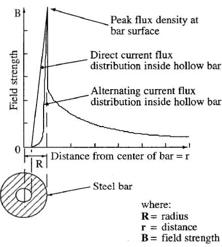
The magnetic field in long, solid and hollow cylinders peaks at
the outside diameter surface for both magnetic and nonmagnetic test
objects. From there, the magnetic field obeys the inverse square law
and decreases by the inverse square of the distance away from the
surface. Field distributions in and around solid and hollow magnetic
conductors are shown in Figures A and B.
Irregularly shaped test objects may have their magnetization
currents tested using direct field indicators to determine optimum
testing conditions. The magnetic field density varies with the shape
of the test object. For test objects of regular but changing diameters,
different current levels may be required to produce an effective
magnetic field. Two or more levels of current are needed to test
objects shaped like these. Automotive crankshafts are examples
where multiple current levels are needed.
FIG A. Field distribution in and
around a solid magnetic conductor
carrying alternating current.
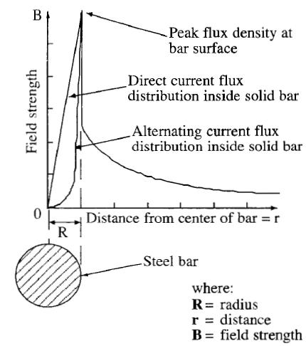
FIG B. Field distribution in and
around a hollow magnetic conductor
carrying alternating current.
Tubular objects may be tested using a central conductor. An
alternate method is to wrap a coil through a long test object and
rotate the test object. Note that several setups may be required for an
effective test.
Test objects containing machined holes or slots may be tested in
many ways. Gears and other machined objects often have holes,
keyways or gear teeth that can effectively be tested by magnetic
particle means. Several set ups may be required that include
different cunent types, strengths and directions, as well as test object
rotations.
Deep holes and sharp gear teeth may be tested by using magnetic
particles suspended in a self curing rubber, a so-called magnetic
rubber. Here, the test object’s residual field must be high or the
current must be applied during the total cure time of the rubber.
When the rubber is carefully peeled away, the magnetic pattern may
be observed frozen in the rubber. The use of fluorescent magnetic
particles enhances this method.
Contact Plates
Contact plates are copper plates that come in contact with the test
object or central conductor. They are primarily used in wet bath
techniques. Contact plates are found in specialized magnetic particle
equipment called wet horizontal bench machines, as shown in
Figure.

Prods
Prods are a specialized form of small contact plates, as shown in
Figure. They are often used to test welds. Prods are firmly
pressed against the surface to be magnetized. As current flows
through that smface, a circular magnetic field is set up around the
prods. Often, wet horizontal bench machines are equipped with
prods for irregular shaped test objects. Small alternating cunent
1000 to 2000 A portable magnetic particle machines are the most
common type of prod testing equipment.

Discontinuity Detection
Discontinuities commonly discovered by circular fields are
generally surface breaking irregularities, with cracks having the
highest probability of detection for all current modes. Near surface
cracks and cracks under coating and galvanization are commonly
detected if the coating is not too thick.
Longitudinal Field
Typically, longitudinal fields are induced in the test object by
coils. Multiple shapes can be easily accommodated. The magnetic
field is produced by current flow in a coil, which is a long,
nonmagnetic conductor wrapped around the test object. The
magnetic test field is greatest at the surface of each line of the coil.
Thus, the test object should be placed near the inside surface of the
wrapped coil. Coil techniques are easily adaptable to a variety of test
object shapes and sizes.
Field Direction
The field in a current carrying coil is the force needed to
successfully magnetize a test object within the coil. It may require
several wraps of the coil or solenoid to build up enough magnetic
flux density for testing.
Field direction produced by a magnetic yoke is between the legs
and is therefore referred to as a longitudinal field in relation to the
yoke. The yoke may be used to magnetize a test object
longitudinally or transversely by changing the orientation of the
legs. A yoke is a temporary horseshoe magnet made of soft, low
retentivity iron that is magnetized by a small coil wound around its
horizontal bar. When the energized yoke is placed on a test object,
the flux flowing from the yoke’s north pole through the test object to
the yoke’s south pole induces a local field in the test object.
However, the magnetic field produced by the yoke does not lie
entirely within the test object. An external field is present that is a
deterrent to locating subsurface discontinuities. If magnetic particles
are applied sparingly at the area between the poles, indications of
surface discontinuities can be detected.
Discontinuities commonly discovered by longitudinal fields
include transverse discontinuities. Transverse discontinuities are
discontinuities oriented perpendicular to the major axis of the test
object. Both alternating current and direct current techniques may be
used, depending on test object shape.