This article is about Medium Voltage Cable Installation and Commissioning (Rated 5KV through 35KV) of Electrical Power System as per International Codes and standards for Commercial Buildings, Plants and Refinery Projects.
Medium Voltage Cable Installation and Commissioning (Rated 5KV through 35KV)
The raceway systems shall be installed complete prior to installation of MV power cables. (NFPA 70, NEC 300.18)
Consult the cable manufacturer for cable maximum allowable / recommended pulling tension. (IEEE 576, 4.1.1.1)
When the calculated pulling tension is close to (or within 10% of) the maximum pulling tension, use tension gauge during pulling. (IEEE 576, 4.1.1.2)
The maximum pulling tension for copper conductor should not exceed 0.008 times circular-mil area. (IEEE 576, 4.1.1)
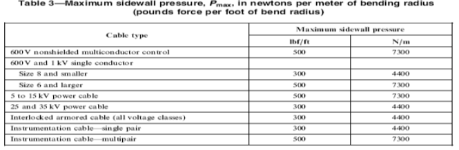
Cable sidewall pressure limitation – The ratio of pulling tension out of the bend to the radius of the bend of the cable shall be limited to minimized cable damage. Table 3 (IEEE 576, 5.1) See Attachment.
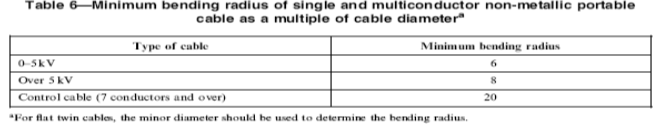
Bending radius of cables without metallic shielding or armor: Table 4 (IEEE 576, 7.1) See Attachment.
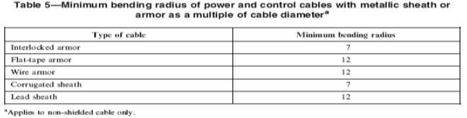
Bending radius of cables with metallic armor: Table 5 (IEEE 576, 7.1) See Attachment.
Ensure adequate clearance between duct or conduit diameter and cable diameter. The percent fill requirement shall not be exceeded. (IEEE 576, 4.5(a))
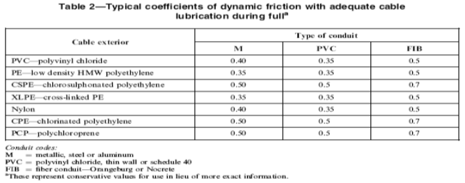
Use adequate lubrication of the proper type to reduce friction in conduit and duct pulls. (IEEE 576, 4.5(b))
“Avoid sharp bending of the cable at the first pulley in overhead installations by locating the pay-off reel far enough away from the first pulley that the lead-in angle is kept relatively flat.
(IEEE 576, 4.5 (c))”
Minimum bending radius for all cables with metallic shield is 12 times the diameter of the individually shielded conductors or 7 times the overall diameter, whichever is greater.( IEEE 576, 7.3)
Conduit shall be sized in accordance with Table 1 in Chapter 9 of the NEC.
“Use a torque-balance pulling line or an adequately sized swivel joint between pulling line and the cable pulling attachment to prevent cable rotation during pulling operations.
(Manufacturer’s Instructions) (NFPA 70, NEC 110.3(B))”
“Avoid abrasion and other damage to cables during installation. Provide physical protection of cables, such as flexible cable guides or feed-in tubes, at the entrance of manholes, underground ducts, and conduits. Use guides adequately sized for the cable being pulled and for the duct, along with properly sized bell and duct adapters.
(Manufacturer’s Instructions) (NFPA 70, NEC 110.3(B))”
Support cable reels with adequately sized reel jacks and reel axle. Ensure cable reels are level to reduce drag. Unreel cable from the top of the reels. Carefully control the rate of cable reel rotation. For large conductors or long pulls, assist reel rotation manually or use a power out reel. Manufacturer’s Instructions) (NFPA 70, NEC 110.3(B))
Cable may be pulled manually for short, easy runs. Use power-assisted cable pulling equipment for long or difficult pull or pulls with several transitions. Pull cable at constant velocity not less than 15 feet per minute and not greater than 50 feet per minute. Do not pull cable with a vehicle. Manufacturer’s Instructions) (NFPA 70, NEC 110.3(B))
“Use basket weave cable grip for cable runs less than 200 feet, for cables less than 2 inches in diameter, and for cables between switchgears and transformers. Do not exceed pulling tension of 1000 pounds per grip. Provide sufficient slack to remove at least one foot of cable beyond the inside end of a basket grip.
(Manufacturer’s Instructions) (NFPA 70, NEC 110.3(B))”
“Use pulling eyes and cable grips together for cables with nonmetallic sheaths, to prevent damage to cable structure.
(Manufacturer’s Instructions) (NFPA 70, NEC 110.3(B))”
“Do not pull cable using metallic shielding wires, tapes or braids, or armor not designed for the purpose. Do not use rope hitches for pulling attachment to cables.
(Manufacturer’s Instructions) (NFPA 70, NEC 110.3(B))”
“Provide mechanical equipment or adequate personnel to feed cables into conduits or ducts to minimize tension at the point of feed. Ensure that cable do not crossover one another at the feed end during the pull.
(Manufacturer’s Instructions) (NFPA 70, NEC 110.3(B))”
Observe cable at all points of duct entry and exit during pulling operation. Use two-way voice communication before and during installation. Stop pulling operation immediately with any indication of binding or obstruction. Do not resume pulling until such difficulty is corrected. Manufacturer’s Instructions) (NFPA 70, NEC 110.3(B))
“Test terminate and energize cable as soon as possible after installation. If cables are left overnight for more than 8 hours after pulling prior to termination, remove the pulling attachment, cut the cable end, reseal the cable immediately with tape, paraffin or shrink wrap caps, and support the cable in a manner which will prevent entrance of moisture into the cable. When sealing with tape completely wrap cable end with rubber tape to 3 inches from the cable end. Cover rubber tape with polyvinylchloride tape.
(Manufacturer’s Instructions) (NFPA 70, NEC 110.3(B))”
GENERAL – Install cables in accordance with cable manufacturer recommendations. (NECA 600) (NFPA 70, NEC 110.3(B))
GENERAL – Make provisions for supplying adequate slack to properly train and support cables. (NECA 600) (NFPA 70, NEC 110.3(B))
GENERAL – Verify the factory high potential test report for the cable prior to installation. (NECA 600) (NFPA 70, NEC 110.3(B))
GENERAL – Do not pull cable into a conduit that already contains conductors. (NECA 600) (NFPA 70, NEC 110.3(B))
GENERAL – Do not reinstall cable removed from a conduit or duct for permanent use. (NECA 600) (NFPA 70, NEC 110.3(B))
“GENERAL – Do not install cable in conduit bodies.
(NECA 600) (NFPA 70, NEC 110.3(B))”
“GENERAL – Clean manholes prior to cable installation.
(NECA 600) (NFPA 70, NEC 110.3(B))”
“CABLE SUPPORTS – Ensure that cable supports conform to contracts documents and are compatible with the environment.
(NECA 600) (NFPA 70, NEC 110.3(B))”
CABLE SUPPORTS – Support cable terminations in a manner so as to maintain their installed position, and to limit the likelihood of the transfer of damaging mechanical stresses to the terminations, equipment or structure. Support cables independently of bushings, insulators, terminations, etc. (NECA 600) (NFPA 70, NEC 110.3(B))
CABLE SUPPORTS – Support cable to maintain required electrical clearances as designed or by the NEC between cables, equipment, structures, ground, etc. Support or suitably protect horizontal run of cables. (NECA 600) (NFPA 70, NEC 110.3(B))
CABLE SUPPORTS – Provide non-metallic cable supports, or galvanized steel channels and brackets and porcelain blocks, and support cable and splices on a maximum of 4-foot centers in manholes. Use heavy duty plastic cable ties suitable for the purpose to secure cables to insulators. (NECA 600) (NFPA 70, NEC 110.3(B))
CABLE BENDING RADIUS – Ensure the radii of bends, termination and splice kits, fittings, cable risers, and other conditions are suitable for the cable and conform fully to the recommendations of the cable manufacturer. (NECA 600) (NFPA 70, NEC 110.3(B))
CABLE BENDING RADIUS – Ensure rollers, sheaves, trolley assemblies, and tube guides have bending radii greater than the minimum bending radius of the cable and do not exceed maximum sidewall pressure. (NECA 600) (NFPA 70, NEC 110.3(B))
“CABLE BENDING RADIUS – Ensure that cable supports conform to contracts documents and are compatible with the environment.
(NECA 600) (NFPA 70, NEC 110.3(B))”
“CABLE BENDING RADIUS – Do not install cables bent or kinked to radius less than recommended dimensions.
(NECA 600) (NFPA 70, NEC 110.3(B))”
“TRANSITIONS – Consults cable manufacturer for recommendations when using sheaves or trolley assemblies to change cable pull directions in manholes, at pullboxes, etc.
(NECA 600) (NFPA 70, NEC 110.3(B))”
“TRANSITIONS – Provide properly sized sheaves, flared duct openings, etc., to ensure proper alignment of cables to conduit or duct system.
(NECA 600) (NFPA 70, NEC 110.3(B))”
TRANSITIONS – Protect cables when pulling through intermediate manholes. (NECA 600) (NFPA 70, NEC 110.3(B))
TRANSITIONS – Maintain minimum bending radius to prevent damage to cables when transitioning from a horizontal run to vertical. (NECA 600) (NFPA 70, NEC 110.3(B))
“TRANSITIONS – Support cables and conductors installed on slopes, in vertical runs, and in risers in a manner to limit the likelihood of damage to conductors, cables and terminations and to limit the likelihood of downhill movement after installation.
(NECA 600) (NFPA 70, NEC 110.3(B))”
TRANSITIONS – Provide conduit and cable supports in junction boxes, raceways, conduit bushings, etc., where cable installed in overhead conduits turn down into terminal enclosures and pull boxes. (NECA 600) (NFPA 70, NEC 110.3(B))
TRANSITI0NS – Maintain adequate depth of cable entering pad mounted equipment, considering the voltage class, until it becomes protected by being directly under the pad, unless suitable mechanical protection is provided. (NECA 600) (NFPA 70, NEC 110.3(B))
“TRANSITIONS – Install cables rising from underground conduits or ducts into pad-mounted equipment to prevent cables from bearing against the edges of a concrete pad openings, conduits, or ductwork.
(NECA 600) (NFPA 70, NEC 110.3(B))”
TRANSITIONS – Provide bushings or adapters where nonmetallic underground conduit with conductors enters a box, fitting, or enclosure to protect the conductors or cable from abrasion, unless the design of the box, firing, or enclosure provides equivalent protection. (NECA 600) (NFPA 70, NEC 110.3(B))
MANHOLES – Support the cable reels on sturdy supports located sufficiently near the manhole to permit feeding the cable through the manhole opening without rubbing on the ground. Locate cable reels at the side of the manhole opening above the duct to receive the cable. (NECA 600) (NFPA 70, NEC 110.3(B))
MANHOLES – Install a flexible tube guide through the manhole opening in a manner that will prevent the cable from rubbing on the edges of the manhole frame, chimney or duct. Note: Consider delaying installations of manhole roofs in new construction to facilitate cable installation. (NECA 600) (NFPA 70, NEC 110.3(B))
MANHOLES – Leave sufficient cable lengths in manholes to permit splicing and training on racks around the manhole walls, and for free movement of the cable due to the expansion or contraction after installation. (NECA 600) (NFPA 70, NEC 110.3(B))
“MANHOLES – Overlap cable ends to provide sufficient undamaged cable for splicing. Overlap each cable to be spliced in manholes at the centerline of the proposed joint by a minimum of 2 feet.
(NECA 600) (NFPA 70, NEC 110.3(B))”
“TRAINING CABLES – Install and secure cables to allow cable movement without destructive concentration of stresses.
(NECA 600) (NFPA 70, NEC 110.3(B))”
“TRAINING CABLES – Use suitable tools for training cables into final position without damage. Do not use conduit hickey for training cables.
(NECA 600) (NFPA 70, NEC 110.3(B))”
TRAINING CABLES – Route cables within switchgear, equipment , junction boxes, manholes, vaults, etc., in a manner which will allow adequate room and working space for bending, terminating and splicing cables. (NECA 600) (NFPA 70, NEC 110.3(B))
TRAINING CABLES – Secure cables in a manner that will not result in cable weight being placed on terminations or splices. Support cable in a manner that does not force cable against grounded metal or which compresses cable diameter. (NECA 600) (NFPA 70, NEC 110.3(B))
“TRAINING CABLES – Where cables are looped around a manhole interior, provide a minimum 360 degrees of cable loop. Where cables are not to be looped in manholes, route cables around manhole walls with the longest distance between points of entry and exit to provide the slack for future cable repairs or splice replacement, if necessary.
(NECA 600) (NFPA 70, NEC 110.3(B))”
“TRAINING CABLES – Train cable to closely parallel walls in manholes, handholes, pillbox, junction boxes, vaults, etc., and to prevent interference to duct entrances or other cables.
(NECA 600) (NFPA 70, NEC 110.3(B))”
“TRAINING CABLES – Provide appropriate insulating barriers where exposed live parts are in an enclosure.
(NECA 600) (NFPA 70, NEC 110.3(B))”
TRAINING CABLES – Where cables enter the top of enclosures, form a drip loop to prevent moisture from running down the cable onto terminations. (NECA 600) (NFPA 70, NEC 110.3(B))
“SPLICES AND TERMINATIONS – Terminate and splice cables in accordance with manufacturer’s recommendations using approved tools and methods. Review design and manufacturer’s prints and instructions prior to starting work.
(NECA 600) (NFPA 70, NEC 110.3(B))”
“Uses Permitted. Type MV cables shall be permitted for use on power systems rated up to 35,000 volts, nominal, as follows:
(1) In wet or dry locations
(2) In raceways
(3) In cable trays as specified in NEC 392.3(B)(1)
(4) Direct buried in accordance with NEC 300.50
(5) In messenger-supported wiring
(NFPA 70, NEC 328.10)”
“Uses Not Permitted. Type MV cable shall not be used unless identified for the use as follows:
(1) Where exposed to direct sunlight
(2) In cable trays
(NFPA 70, NEC 328.12)”
“Minimum Bending Radius for Permanent Training – Tape Shielded Cable — The minimum bending radius for tape shielded cables given below applies to helically applied flat tape or longitudinally applied corrugated tape or combination tape and wire shielded cables. The minimum bend radius to which insulated cables may be bent for permanent training during installation is twelve times the overall diameter for single conductor cable. For multiplexed single conductor cables, the minimum bending radius is twelve times the diameter of the individual conductor or seven times the overall diameter, whichever is greater.
(ICEA-97-682 Appendix E2.1)”
“Minimum bending Radius for Permanent Training – Wire Shielded Cable — The minimum bend radius to which insulated cables may be bent for permanent training during installation is eight times the overall diameter for single conductor cable. For multiplexed single conductor cables, the minimum bending radius is eight times the diameter of the individual conductor or five times the overall diameter, whichever is greater.
(ICEA-97-682 Appendix E2.2)”
Minimum Bending Radius For Permanent Training -Lead Sheath — The minimum bend radius to which insulated cables may be bent for permanent training during installation is twelve times the overall diameter for single conductor cable. For multiplexed single conductor cables, the minimum bending radius is twelve times the diameter of the individual conductor or seven times the overall diameter, whichever is greater. (ICEA-97-682 Appendix E2.3)
PULLING GRIP – A basket-weave grip shall be used for relatively light pulls only. (IEEE 576, 4.1.2)
PULLING GRIP- Non-Metallic Sheathed Cables — The smaller sizes of non-metallic sheathed cables shall be gripped directly by the conductors by forming them into a loop to which the pull wire or rope can be attached. The insulation on each conductor is removed before the loop is formed. Larger sizes are more easily handled by applying a pulling grip over the cable or cables, provided the pull is not too severe. if more than more than one cable is involved, the ends should be bound together with a friction tape before applying the grip overall. Long hard pulls will necessitate the use of pulling eyes . (IEEE 576, 4.6.1)
PULLING GRIP – Armor Cables — In pulling armor cable it is necessary to grip to grip the armor and the conductors. This can be accomplished in a number of ways. One method requires that a portion of the armor be removed. Friction tape is then applied over the armor and down over the conductors, and a long basket weave grip is applied in such a way that it grips both the armor and the conductors. Another method requires that two holes be drilled through the cable (armor and conductors) at right angles to each other and that a loop be formed by passing steel wires through the holes and out over the end of the cable. A third approach would be to use a pulling eye and a grip together, the grip being applied over the armor to prevent its slipping back. The armor is not a tension member. Be certain pulling load is taken by the conductors. (IEEE 576, 4.6.3)
MINIMIZING PULLING TENSION – In order to minimize the pulling tension on the cable’s), the cable should be fed into the duct run from the end nearest the bend. (IEEE 576, 4.5)
After installation, check to determine that end seals are still intact and have not been damaged to the point where water could enter. Apply plastic or rubber tape to help protect against invisible damage if the cable will be subjected to immersion or rain. This is particularly important if there will be a delay of some time between the pulling operation and splicing and terminating. (IEEE 576, 4.5 (d))
“Jam Ratio – A check should be made by computing the ratio between the conduit inside diameter (D) and a single conductor overall diameter (d) to evaluate the potential for jamming. Because bending a cylinder produces an oval cross-section in the bend, use 1.05D for the conduit inside diameter. Evaluate for the jam ratio as follows,
If 1.05D/d is larger than 3.0, jamming is impossible.
If 1.05D/d is between 2.8 and 3.0, jamming is probable.
If 1.05D/d is less than 2.5, jamming is impossible but check clearance.
Note: Avoid jam ratios of 2.8 to 3.2 for extruded dielectric cables. (IEEE 576, 6.1)”
Insulation Shielding. Metallic and semiconducting insulation shielding components of shielded cables shall be removed for a distance dependent on the circuit voltage and insulation. Stress reduction means shall be provided at all terminations of factory-applied shielding. Metallic shielding components such as tapes, wires, or braids, or combinations thereof, and their associated conducting or semiconducting components shall be grounded. (NFPA 70, NEC 300.40)
The grounding of shields, sheaths, armor and other materials in cable systems shall be in accordance with SAES-P-111.
FIREPROOFING – Fireproofing of cables shall be in accordance with SAES-B-006 (onshore facilities) or SAES-B-009 (offshore facilities).
FIREPROOFING – Power cables shall be inherently fireproof to meet UL 2196 fire test procedure for 20 minutes. External fireproofing is not acceptable.
TERMINATION IDENTIFICATION – Identification of cables shall include the cable number and destination (e.g., load equipment tag number).
TERMINATION IDENTIFICATION – Individual phases of power circuits shall be identified by color coding or other means (e.g., marked A, B and C). Neutral (grounded) conductors shall be identified by colors white or grey, and insulated grounding conductors by colors green or green with yellow stripes.
TERMINATION IDENTIFICATION – Wires at termination points shall be identified by the use of permanently imprinted or embossed wire markers of the heat-shrinkable or slip-on type. Slip-on wire markers shall be sufficiently tight so that they will not slip unintentionally. Wrap-around, rigid snap-on, or adhesive type markers are not permitted for wire or cable identification. Cables may be identified by special plastic labels held with cable ties, or similar methods. Colored insulating tapes may be used for phase identification of power circuit conductors.
TERMINATIONS – Stress relief shall be provided at terminations of cables with insulation shields.
MINIMUM CREEPAGE DISTANCE – Medium voltage terminations (operating at 2.4 kV and above) installed outdoors shall have a minimum creepage distance to ground of 40 mm per kV line-to-line nominal system voltage.
MINIMUM CREEPAGE DISTANCE – Medium voltage terminations installed indoors shall have a minimum creepage distance to ground of 25 mm per kV line-to-line nominal system voltage.
UNDERGROUND CABLE – Minimum Cover Requirements — When direct-buried cable, the minimum depth of burial requirement for MV power cable shall be 920 mm from grade level to the top surface of the cable.
UNDERGROUND CABLE – Minimum Cover Requirement — When the MV power cable is run into direct-buried PVC conduit, the minimum depth of burial requirement shall be 610 mm from grade level to the top surface of the conduit.
UNDERGROUND CABLE – Minimum Cover Requirement Under Roads where GI-1021.000 Applies — When the MV power cable is run into direct-buried PVC conduit, the minimum depth of burial requirement shall be 1051 mm from grade level to the top surface of the direct buried PVC, unless a reinforced concrete slab is installed on top of it. NOTE: Exception may be granted by the manager of the Saudi Aramco Department responsible for the road, in which case the 610 mm value above apply.
UNDERGROUND CABLE – Minimum Cover Requirement — When the MV power cable is run into a duct bank, the minimum depth of burial requirement shall be 460 mm from grade level to the top surface of the duct bank.
UNDERGROUND CABLE – Minimum Cover Requirement Under Roads — When the MV power cable is run into a duct bank or rigid steel conduit, the minimum depth of burial requirement shall be 610 mm from grade level to the top surface of the duct bank or rigid steel conduit.
UNDERGROUND CABLE – Minimum Cover Requirement Under Roads Where GI-1021.000 Applies — When the MV power cable is run into a duct bank or rigid steel conduit, the minimum depth of burial requirement shall be 1015 mm from grade level to the top surface of the duct bank or rigid steel conduit unless a reinforced concrete slab is installed on top of it. NOTE: Exception may be granted by the manager of the Saudi Aramco Department responsible for the road, in which case the 610 mm value apply.
UNDERGROUND CABLE – Cables entering buildings shall comply with Paragraphs 5.2 and 5.4 of SAES-B-008. (See also Section 15.4)
“UNDERGROUND CABLE – The location of underground cable shall be marked in accordance with Standard Drawings AB-036273 or AB-036326. Exception:
No underground cable markers are necessary inside switchyards and under elevated substations. ”
“UNDERGROUND CABLE – Manholes containing cables rated 5 kV and above shall be in accordance with Standard Drawing AA-036025.
Exception:
Manholes containing cables rated 5 kV and above, having different shape and size but equivalent structural strength to Standard Drawing AA-036025 manholes (same wall thickness, etc.), are permitted, with the approval of the Electrical Standards Committee Chairman.”
“UNDERGROUND CABLE – Cables that cross under paved roads, concrete slabs, railroads, or other areas that would require extensive or impractical excavations to replace, shall be run in duct banks or in PVC sleeves.
Commentary Note:
Asphalt-paved parking lots and plant areas paved with asphalt for soil stabilization are not within the scope of this Paragraph. No duct banks or sleeves are required in these cases.”
UNDERGROUND CABLE – Cables crossing pipeline corridors shall be installed in accordance with SAES-B-064.
UNDERGROUND CABLE – The minimum crossing or parallel clearance between direct buried cables or conduits and underground piping, including hydrocarbon pipelines that fall outside the scope of SAES-B-064, shall be 300 mm. For direct buried cables, the same reduction is permitted if the cable is installed in a PVC sleeve at the crossing. Direct buried cables shall not be installed directly above or below parallel underground piping.
UNDERGROUND CABLE – Direct buried cables shall be installed in a single layer, except where rearrangement is necessary at transitions to multi-layer concrete encased duct banks or for entering buildings.
UNDERGROUND CABLE – Installation of cables in outdoor concrete-walled trenches with metal or concrete slab covers is not permitted.
UNDERGROUND CABLE – Precast 50 mm thick red concrete tiles, red plastic tiles (12 mm minimum thickness), or PVC coated steel fence fabric shall be placed 300 mm above direct buried cable, in accordance with Standard Drawing AD-036874. In addition, a yellow warning tape shall be installed over the tiles or fence fabric.
UNDERGROUND CABLE – Backfill containing large rocks, paving materials, cinders, large or sharply angular substances, or corrosive materials shall not be placed in an excavation where materials can damage cables, or prevent adequate compaction of fill, or contribute to corrosion of cables. Protection in the form of granular or selected material or suitable sleeves shall be provided to prevent physical damage to the cable.(NFPA 70, NEC 300.5 (E)
MINIMUM SEPARATION – Minimum separation (above or below ground) between a power cable operating at 1000 V or above, up to 34.5 kV, and a parallel or crossing power or control cable operating at less than 1000 V, shall be 300 mm, except when the medium voltage cable is armored or metal clad or is installed in rigid steel conduit, or is installed in aluminum cable tray and is separated from the lower voltage cable by solid fixed metallic barriers, or when the low voltage cable is installed in rigid steel conduit.
MINIMUM SEPARATION – Minimum separation requirements between a power and any communication conductors shall be in accordance with SAES-T-911 or SAES-T-928.
MINIMUM SEPARATION – Minimum separation (above or below ground) between any cable operating at above 34.5 kV, and cables operating at or below 34.5 kV, shall be 1 m.
BELOW GRADE CABLE ENTRY INTO BLDGS IN HYDROCARBON PROCESSING PLANTS – Penetration of the wall of the building basement or underfloor space shall be via short horizontal sections of PVC conduits (sleeves) that will be encased or grouted into the wall.
BELOW GRADE CABLE ENTRY INTO BLDGS IN HYDROCARBON PROCESSING PLANTS – The inside of the sleeves shall be sealed with 3M Scotchcast Brand 4416 Cable Duct Sealing Kits, with an additional layer of 3M Brand Fire Barrier CP 25N/S Caulk to provide fire retardancy on the building interior side.
BELOW GRADE CABLE ENTRY INTO BLDGS IN HYDROCARBON PROCESSING PLANTS – The cables outside the building shall be direct buried for a distance of at least 2 meters (see also Paragraph 10.14).
“BELOW GRADE CABLE ENTRY INTO BLDGS IN HYDROCARBON PROCESSING PLANTS – Multi-conductor cable penetrations shall be made with intact cable jackets. If individual conductors are required to be sealed by other Saudi Aramco standards, the sealing shall be done at the most convenient location inside the building using Raychem CBK cable blocking kits, Raychem DWBS water blocking system kits, or equivalent. Commentary:
If cables or conduits entering buildings are required to be sealed by the NEC, sealing must meet requirements of the NEC and Paragraphs 15.1, 15.2 and/or 15.3 above.”
“INSTALLATION – Shielded Cables and Nonshielded Cables in Metal- Sheathed Cable Assemblies. Underground cables, including nonshielded, Type MC and moisture-impervious metal sheath cables, shall have those sheaths grounded through an effective grounding path meeting the requirements of NEC 250.4(A)(5) or 250.4(B)(4). They shall be direct buried or installed in raceways identified for the use.
(NFPA 70, NEC 300.50 (A) (1))”
INSTALLATION – Other Nonshielded Cables. Other nonshielded cables not covered in 300.50(A)(1) shall be installed in rigid metal conduit, intermediate metal conduit, or rigid nonmetallic conduit encased in not less than 75 mm (3 in.) of concrete. (NFPA 70, NEC 300.50 (A) (2))
“CABLE SPLICING – Direct burial cables shall be permitted to be spliced or tapped without the use of splice boxes, provided they are installed using materials suitable for the application. The taps and splices shall be watertight and protected from mechanical damage. Where cables are shielded, the shielding shall be continuous across the splice or tap.
Exception: At splices of an engineered cabling system, metallic shields of direct-buried single-conductor cables with maintained spacing between phases shall be permitted to be interrupted and overlapped. Where shields are interrupted and overlapped, each shield section shall be grounded at one point. (NFPA 70, NEC 300.5 (C))”
CABLE SPLICING – Splicing of conductors shall be kept to a minimum. The maximum number of field splices permitted in any one circuit for new installations of cables rated above 1000 V (excluding submarine cables) is the number made necessary by the use of standard size reels with full length cables, plus one extra splice. In case of accidental damage of the cable during installation, additional splices are permitted with the concurrence of the cable Proponent.
“GROUNDING – Shields and armor of power cable shall be grounded at both ends. Continuity at splices shall be maintained by bonding across the splice.
Commentary:
Installation of voltage limiters may be necessary if cable shields and armor are not grounded at both ends.”
Pre-commissioning
CONTINUITY TEST FOR CABLE SHIELD AND CONDUCTOR – For shielded power cable, continuity test shall be performed on each conductor and the shield.
TESTING FOR NEW CABLES AND SPLICES – New installations of cable and splices shall be 5 kV megger tested between each conductor, and each conductor and the shield (for shielded-cable) and then DC high-potential tested after installation at voltage levels specified in 15-SAMSS-502 and listed in Table 3.
TESTING OF NEW CABLE TO BE SPLICED TO EXISTING CABLE – New cables to be spliced to existing cables shall be megger tested and DC high-potential tested prior to splicing. After splicing, the new and existing cable combination shall be 5 kV megger tested. In addition, if the existing cable has been in service for less than five years, the new and existing cable combination shall be high-potential tested to the voltage listed in Table 3.
TESTING OF EXISTING MV CABLES – Under special circumstances, as determined by the cable Proponent, an existing or old cable may be 5 kV megger tested, and, if it has been in service for less than five years, it may be high-potential tested to the voltage listed in Table 3. DC high-potential testing shall not be performed on cables that have been in service for more than five years.
“HIGH-POTENTIAL TEST AFTER MOUNTING OR FORMING THE TERMINATIONS – The high potential test on medium voltage cables may be performed after mounting or forming the terminations, provided:
(i) terminations have creepage distances
(ii) terminations are not connected to equipment, unless the equipment can also be tested at the same voltage; and
(iii) there are sufficient clearances from enclosures and other adjacent objects.”
“HIGH POTENTIAL TESTS AFTER INSTALLATION OF ELBOW CONNECTORS – If separable connectors (elbows) conforming to ANSI/IEEE 386 are used, the high potential test on medium voltage cables may, at the request of the cable Proponent, be performed after installation of the elbows. In this case:
(i) the test must be performed with the elbows plugged into insulated parking bushings; and
(ii) test voltage shall be the lesser of the ICEA cable test voltage listed in Table 3 and the ANSI/IEEE 386 DC withstand voltage.
Commentary Notes:
A) For new 15 kV cable, when tested with elbows, the test voltage is reduced from 64 kV to 53 kV DC; for 35 kV cable it remains unchanged at 100 kV DC (the ICEA cable test value);
B) If 200 A elbows are installed on both ends of the cable, a feed-thru bushing instead of one of the two parking bushings may be used to apply the test voltage;
C) In most cases, it is chosen to test the cables without the elbows.”
The integrity of the overall jacket of direct buried cables rated 5 kV and higher shall be tested by conducting a 5 kV megger or high potential test between the cable insulation metallic shield (and sheath or armor, if any) and ground. (See Attachment, Table 11)
International Standard and Codes for Medium Voltage Cable Installation and Commissioning
- Non-Hazardous Indoor Enclosures, Installation and Pre-Commissioning
- Boxes, Enclosures, and Accessories Materials Selection & Requirements
- NFPA 70 National Electrical Code (NEC), 2008 Edition
- NECA 600 Recommended Practice for Installing and Maintaining Medium Voltage Cable, 2003
- IEEE 576 IEEE Recommended Practice for Installation, Termination, and Testing of Insulated Power Cables as Used in the Petroleum and Chemical Industry, 2000 Edition.
1. Attachment – 1 IEEE 576 – 2000, Tables 2, 3, 5, 6, 9 and 11