This article is about Metallic Wireways and Accessories Materials Selection & Requirements of General Boxes and Enclosures for Electrical Power System Systems as per International Codes and standards for Commercial Buildings, Plants and Refinery Projects.
Metallic Wireways and Accessories Materials Selection & Requirements
Material Requirements
- Marking:
Metal wireways shall be marked so that their manufacturer’s name or trademark will be visible after installation.
[NFPA 70, NEC 376.120]” - Metal wireways shall be permitted in the following:
(1) For exposed work
(2) In concealed spaces as permitted in 376.10(4)
(3) In hazardous (classified) locations as permitted by 501.10(B) for Class I, Division 2 locations; 502.10(B) for Class II, Division 2 locations; and 504.20 for intrinsically safe wiring. Where installed in wet locations,
wireways shall be listed for the purpose.
(4) As extensions to pass transversely through walls if the length passing through the wall is unbroken. Access to the conductors shall be maintained on both sides of the wall. [NFPA 70, NEC 376.10] - Metal wireways shall not be used in the following:
(1) Where subject to severe physical damage
(2) Where subject to severe corrosive environments [NFPA 70, NEC 376.12] - Wireways, auxiliary gutters, and associated fittings shall employ materials that are acceptable for the particular use, and shall be made and finished with the degree of uniformity and grade of workmanship practicable in a well-equipped factory. [UL 870 Sec. 5.2]
- A wireway system shall include all wireways and fittings required to make a complete installation in accordance with the National Electrical Code, ANSI/NFPA 70. [UL 870 Sec. 5.3]
- Electrical materials shall be new and unused.
- Electrical materials shall be in accordance with the Saudi Aramco-approved project-specific design drawings, diagrams, schedules, lists, databases, and associated documents (in particular, raceway type and trade size as shown on electrical BOM and raceway schedules).
- Electrical materials shall be free of damage.
- Electrical materials shall conform to all applicable requirements, standards, and specifications prior to release to be used as part of the work.
- Electrical materials shall be identified by using tags, stamps, color coding, stencils or labels. The location and method of identification shall not affect the function or quality of the materials.
- Electrical materials shall be traceable from the manufacturer and supplier through delivery, storage, fabrication, erection, installation, repair, modification and use.
- The interior of the wireway shall be free from burrs and sharp corners or edges that may abrade the insulation on conductors or otherwise damage wiring. Screws and bolts, however used, shall not project
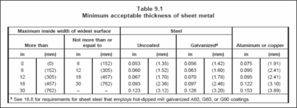
into the wireway unless sharp ends and threaded sections are covered or otherwise prevented from coming in contact with wires. [UL 870 Sec. 6.3] - A sheet-metal enclosure shall have a thickness not less than that specified in Table 9.1 (Attachment 1). [UL 870 Sec. 9.1]
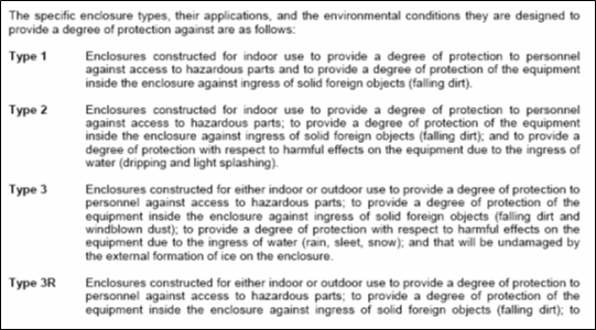
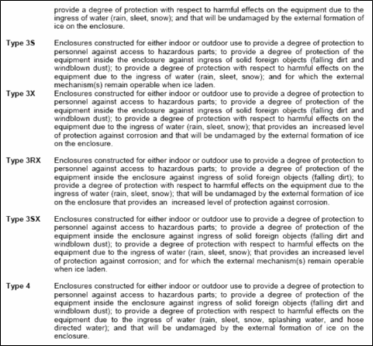
- The features of each enclosure type are applicable only when the enclosure is completely and properly installed. Enclosure type shall be as specified in attachment 2. [NEMA 250 Sec. 2]
- A cover shall be provided with means for securely holding it in place on the trough. [UL 870 Sec. 12.1]
- The fastenings shall be located not more than 6 in (152 mm) from each end of the cover and spaced not more than 12 in (305 mm) apart at points between the end fastenings. [UL 870 Sec. 12.2]
- A fastening device other than a tapped hole or nut may be employed with a screw. A type of fastening other than a screw may be employed if it is of adequate strength and is otherwise suitable for the application. [UL 870 Sec. 12.3]
- Unless a cover complies with the requirements in 12.5, a hinged or screw-on cover shall have flanges that overlap the side walls of the trough not less than 7/16 in (11.1 mm) throughout the full length of the cover. The ends of such a cover shall:
a) Be flanged or otherwise formed to overlap the trough at least 1/2 in (12.7 mm),
b) Provide a 1/4-in (6.4-mm) rabbet, or
c) Employ a construction affording an equivalent closure of the trough. [UL 870 Sec. 12.4]” - A flat, unhinged cover may be used if:
a) Each side wall of the trough is flanged at right angles to the wall to overlap the cover not less than 1/2 in (12.7 mm),
b) Each end of the cover forms a 1/4-in (6.4-mm) rabbet with the adjoining cover, and
c) The cover is fastened to the trough as required by 12.2. [UL 870 Sec. 12.5] - “A hinge for a door or cover shall be of metal not less than 0.054-in (1.37-mm) thick if made of steel, and not less than 0.077-in (1.96-mm) thick if made of copper or aluminum. [UL 870 Sec. 13.1]
- Hinges shall not be spaced more than 24 in (610 mm) apart, measured center to center, and not more than 15 in (381 mm) from each end of the cover. At least two hinges shall be used for each cover.
Exception: A single hinge that extends the full length of the cover may be used. [UL 870 Sec. 13.2]” - A hinged door or cover shall be provided with at least one latch or the equivalent for each 30 in (762 mm) or less of cover length. Latches shall not be located more than 12 in (305 mm) from each end of the cover and shall be evenly spaced not more than 36 in (914 mm) apart at points between the end latches. [UL 870 Sec. 13.3]
- Unless a wireway enclosure is made of metal that will resist corrosion, both inside and outside surfaces of the trough and the cover shall be protected against corrosion by enameling, galvanizing, plating, or other equivalent means. [UL 870 Sec. 16.1]
- The enclosure of a raintight wireway shall be protected against corrosion by one of the following coatings:
a) Hot-dipped mill-galvanized sheet steel conforming with the coating Designation G90 in the Weight [Mass] of Coating Requirements Table in the Standard Specification for Steel Sheet, Zinc-Coated (Galvanized) or Zinc-Iron Alloy-Coated (Galvannealed) by the Hot-Dip Process, ASTM A653, with not less than 40% of the zinc on any side, based on the minimum single-spot test requirement in this ASTM designation.
b) A zinc coating, other than that provided on hot-dipped mill-galvanized sheet steel, uniformly applied to an average thickness of not less than 0.00061 in (15.5 μm) on each surface with a minimum thickness of 0.00054 in (13.7 μm). [UL 870 Sec. 16.4] - A raintight wireway shall be constructed to exclude a beating rain. [UL 870 Sec. 17.1]”
- There shall be provision for drainage of a raintight wireway. [UL 870 Sec. 17.3]
- A raintight wireway shall be provided with external fastening means for mounting. [UL 870 Sec. 17.4]
International Standard and Codes for Boxes, Enclosures, and Accessories
- METHOD STATEMENT FOR TESTING & COMMISSIONING OF SWITCHGEAR
- Advanced Power and Energy Meters Technical Requirements
3. NFPA 70 – National Electrical Code (NEC).
4. SAES-P-104 – Wiring Methods and Materials.
5. SAES-P-100 – Basic Power System Design Criteria.
6. UL 870 – Wireways, Auxiliary Gutters and Associated Fittings.
7. NEMA 250 – Enclosures for Electrical Equipment (1000 V max)
1. Attachment 1: Table 9.1 – Minimum Acceptable Thickness of Sheet Metal – UL 870
2. Attachment 2: Specific Enclosure Types – NEMA 250


