This article is about Method Statement for Concrete Work Including Form work & Rebar Works and Coating.
Do you know, What is method statement? A written document that gives specific instructions on how to safety perform a work-related task, or operate a piece of plant or equipment.
What is Method Statement for Concrete Work?
This method statement is made to enumerate the work activities related to the formwork, rebar work, and concrete work for and also to ensure safe execution of all work activities in accordance with the requirements of Contractor/ Company in commercial buildings, plants and refineries.
The purpose of this article is to form Company and concerned parties of the works that will take place inside the Company compound. Information and quick understanding of the works to be performed will be provided to the personnel involved.
The objective of the work activities enumerated herein is to facilitate the construction structure and plant facilities under the above referenced project.
1. Work Scope.
The latest revision of Company’s Project Specifications shall be used as references and shall be the part of this Method of Statement during work execution. This instruction Encompasses all the work activities related to concrete work which includes.
► Form work.
► Rebar work.
► Concreting Casting.
► Coating and Curing.
2. Tools and Equipment.
Following tools and equipment are used in the Concrete Work Method Statement.
All equipment and tools being mobilized on site shall be certified and in good and running condition and have PWAS. They shall be double checked and inspected by contractor prior to use. Equipment operators and drivers shall have current licenses and valid certificate to run equipment. Listed below are the tools and equipment to be used. All heavy equipment as required will be fitted with PWAS.
Tools and equipment for formwork are to include measuring tapes/ rulers, hammers, spirit levels, squares (combination/ tri), nail bags, hand saws, string lines, shovels, marking equipment, pinch bars, automatics levels, power saws, power drills, nail guns, air compressors and hoses, water-jet, power lead, spanners, etc.
Tools and equipment for rebar work are to include portable rebar cutter, bolt cutters, wire nippers, tie wire reels, measuring tapes/ rulers, and reinforcement benders, mesh guillotines, and may include a range of general hand and power tools, etc.
Tools and equipment for concrete work are to include measuring tapes/rulers, hammers, spirit levels, shovels, lake, marking equipment, automatic levels, aluminum bar, wheel barrow, trowel, vibrator, etc.
Construction mobile equipment shall be inspected. All equipment will be inspected monthly and if found in good condition will be color coded any damaged or, site made tools will be destroyed.
3. Work Procedure and Method Statement.
We will be discussed here 3 more sub works method statement of concrete work method statement.
3.1 Rebar Work Method Statement.
1. Material.
(1) REBAR
Material steel bar shall conform to SASO SSA2, and shall be hot-rolled, epoxy coated, high tensile, deformed steel with minimum yield strength of 4286kf/cm² (420MPa, 60ksi), which is equivalent to ASTM A615 / ASTM A615M for normal rebar and ASTM A 706M for seismic rebar.
(2) SPACERS AND TIE WIRE
Spacers should be of such materials and designs as well as durable, not lead to corrosion of the reinforcement and keep the concrete cover.
Spacers; Approved plastic pipe spacer and/ or Concrete spacer which are made at the site that material should be the same as structure concrete.
Tie wire: Galvanized soft cooling wire 0.8mm~1.4mm diameter.
2. Bar Bending / Cutting.
- Fabrication of rebar shall be in accordance with D-000-1340-0011_OF1. Standard Drawing for Rebar Arrangement.
- Rebar cutting & Bending will be done at the site work shop.
- Secure the latest drawing regarding the shape. Dimension and diameter of bars for the required reinforcement.
- Mark the correct length and cut & bend the bars in-group of items having the same lengths and sizes.
- Secure the fabricated rebar in bundles properly marking them with non-metallic logs indicating the structure, the mark number, shape code, diameter of bar, length and bar quantity.
- Random-length straight bars shall also be tagged to show number of bars, size and length.
3. Rebar Fixing.
- Reinforcing splicing shall be in accordance with D-000-1340-011_0F1, unless otherwise noted on the detail drawings.
- Clean the rebar of any soil, mud, or oil or other materials that may adversely affect or reduce the bond between the bar and the concrete.
- Place the reinforcing bars to correct positions as marked on site and fix.
- Make sure that the spacing, concrete cover thickness overlapping locations and overlapping length are in accordance to the specified requirements.
- Fix the cover spacers firmly to prevent getting displaced during concrete pouring and to maintain the required concrete cover for the reinforcement.
- Minimum concrete Cover.
| Concrete Structure | Minimum Cover (mm) |
| 1) Concrete cast against and permanently exposed to earth Others (including foundations over A sub-slab). | 75 |
| 2) Formed concrete exposed to earth or weather. Supporting Process Equipment. Buildings, walkways platforms, stairs, AC pads. | 75 50 |
| 3) Concrete not exposed to weather or in contact with ground (which can be inspected from all sides). Beams, columns. Slabs, walls, joints. | 50 25 |
| 4) Concrete exposed to sea water, raw water, or sewage. | 75 |
| 5) Between reinforcement and anchor flange/pipe Within pipeline anchor blocks. | 100 |
| 6) Concrete slab over 50mm lean concrete, or plasticized sheet. | 50 |
| 7) Sidewalks, walkways, etc. | 50 |
Proper and safe platforms with access ladder must be erected prior to installation of elevated areas. Use chairs to support tops mat of slab reinforcement or any structure with top and bottom reinforcement.
No welding allowed for purpose of rebar installation/splicing. Water splashing shall be conducted on the rebar based on condition in summer season.
3.2 Form work and Shoring MS.
1. Materials.
- Main material: Plywood, Timber, Dakar Beam, Aluminum Beam.
- Accessory: Tie bolt, nut.
- Shoring material: Prop pipe support, Timber, Scaffolding Pipe.
2. Form Shuttering & Shoring.
- Formwork shall be conforming to shape, lines grade and dimensions indicated on the latest revision of approved construction drawings.
- Formwork shall include the forming of all openings, pockets, embedded items sleeves, angles, bolts, and other accessories.
- All formworks materials shall be water tight, made out of sound approved materials and properly braced, strutted and shored during the construction.
- Formwork shall be cleaned free from any hazards and temporary opening to be provided where necessary to drain away water and rubbish.
- All formwork shall be rigidly constructed and sufficiently tight to prevent any leakage of grout or mortar.
- On the other edges of exposed concrete members and foundations, 25mm Chamfer shall be placed in forms in accordance to the latest revision of approved drawing for construction or project specification.
- Before placing the concrete, all debris shall be removed from inside the forms, internal faces of formwork shall be coated with a suitable oil release agent to prevent adhesion of the concrete, providing this preparation shall not stain finished concrete surface and not to be in-contact of the reinforcement steel.
- Formwork shall be inspected and approved by COMPANY and/or CONTRACTOR before casting concrete.
- Proper access & Scaffolding should be provided.
- Tolerances for formed surface shall be complied with project Specification.
3.3 Concrete Pouring Method Statement.
1. Material.
(1) Admixtures.
Admixtures conforming ASTM C260 and/or high range water-reducing admixtures to ASTM C494 type For G can be added to the ready-mixed concrete.
(2) Cement
Cement shall be Ordinary Portland Cement Type I conforming to SASO SSA 143 and the optional chemical requirements of ASTM C150, Table 2
(3) Ready Mixed Concrete
All concrete shall be ready mixed concrete, in accordance with ASTM C94, batched at approved mixing plant. Design of reinforced concrete foundations and structures shall comply with ACI 318-08.
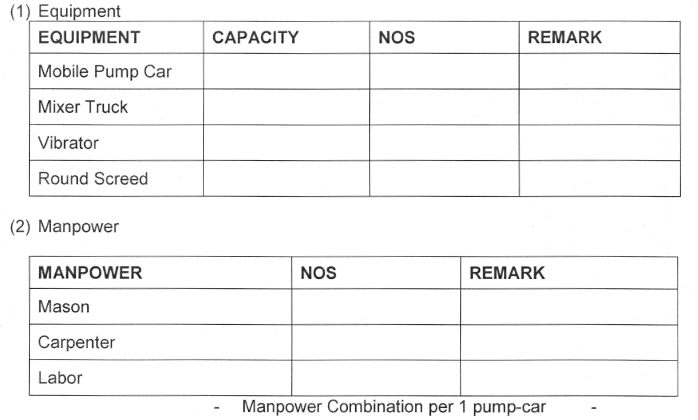
2. Equipment and Manpower.
(1) Equipment
(2) Manpower
3. Before, During & After Concrete Placing.
- Each days pour shall be properly scheduled to ensure that all work has been completed and inspected by Civil QC Inspector of Company & Contractor to proceed for concrete pouring, adequate manpower and equipment.
- Curing Mat. PVC Sheet, Styrofoam, Water Tanker should be prepared prior to concrete placing works commencing.
- Two ready mixed concrete trucks per one pump car shall be planned as the normal radio. Rates of placing shall be carefully determined to ensure continuous supply of concrete.
- Concrete shall be poured continuously to avoid cold joint.
- To prevent separation of aggregate concrete shall be placed as near as possible to its final location.
- Concrete shall not be dropped freely from a height in excess of 1meter.
- After completion of concrete placing the following shall be checked.
- Concrete cover to reinforcement starter bars is correct and have not been displaced during pouring works.
- Embedded plates and bolts are in the correct location. This will be verified by the Surveyor or Engineer immediately after placing concrete is complete.
- Kickers and haunches have been vibrated at the top and finished to achieve a dense homogenous concrete mass.
- After concrete has been consolidated, trowel finishing shall be performed at the top of concrete.
4. Vibrating Compaction of Concrete.
- Maximum height of pouring each layer shall not exceed 450mm.
- Vibrator shall be inserted vertically, shall penetrate the rapidly to the bottom of the uppermost layer and at least 150mm into the previous lift.
- Insertion of the vibrator shall be such that the fields of action shall overlap.
- Vibration shall stop when the concrete surface takes on sheen, large air bubbles no longer escape, the vibrator pitch or tones changes or the vibrator action changes.
- The vibrator shall not be forced into the concrete or not be used to move the concrete along the form or from one location to another.
- The poker vibrator head shall not be held against the reinforcement. This may cause the bond between the rebar and concrete already setting to weaken.
- Care shall be taken that the vibrator shall not loosen bolts of the form ties.
- Wood hammer can be used to compact the outside of the frame, only as additional compaction due to lack of efficiency.
- Vibrator shall touch neither the rebar nor the forms during placing of concrete.
- Concrete shall be vibrated around rebar and into pockets to form a homogenous mass without any voids. Special care shall be taken to vibrate concrete around box-outs, pipe sleeves and penetrations embedded.
- Trained flagman will be deployed to manage concrete truck movements.
- To minimize concrete spill PVC sheet is to be placed at the rear of the concrete pump.
- Truck mixers must either wash out in a dedicated controlled area next to the pour area or they return to the batching plant and wash out there.
5. Form Stripping & Curing.
- Metal ties and anchorage within the form shall be constructed to permit removal to a depth of at least 50mm from the face without injury to the concrete.
- The cavities of tie holes shall be filled with cement mortar and surface left sound, mouth without cracks, even, and uniform the concrete.
- Concrete shall be cured in accordance with ACI 308 with minimum curing period of 4 days.
- Where water curing is selected the concrete shall be maintained wet with portable water for 7 days.
- Use of curing compound shall be subjected to the Company approval considering the properties of the compound, adhesion to the coating required for underground foundations, protection of construction joints and climatic conditions.
6. Coating & Protection.
- A plasticized sheet vapor barrier, minimum 0.15mm (6mils) in thickness, or a 50mm sub-slab (lean concrete) shall be placed beneath concrete foundations.
- All concrete surface in direct contact with earth shall be coated with two coats of PPCS-10 specified in D-000-1340-011_0F1. Concrete surfaces exposed to atmosphere up to 500mm above grade level shall be coated with two coats of APCS-3, which can also be applied on concrete surfaces below grade instead of APCS-10.
7. Responsibilities.
7.1 Site Manager.
The site manager is responsible for implementing HSE at the job site.
7.2 QA/QC Site Manager.
The QA/QC Site Manager shall be responsible for ensuring that works are carried out in accordance with relevant procedures, ITP and quality requirements.
7.3 HSE Supervisor.
HSE Supervisor is responsible for ensuring implementation of HSE.
7.4 Site Building Engineer.
The Site Building Engineer has the overall responsibility for the implementation of work as per approved drawings. He shall arrange the manpower, equipment and materials required for the implementation of the works, coordinate with HSE Officer and QA/QC Site Manager involved in the tasks in accordance to the method statement.
7.5 Site Supervisor.
The Site Supervisor is the in-charge for the implementation of the work activities as per approved drawings. Also, the Site Supervisor is responsible for securing and closing out of all PTWs,
7.6 Q.C Inspector.
The Surveyor (Inspector) is responsible for stake out the locations / boundaries, elevation, alignment and other related survey activities.
8. Safety Action Plan.
- Sub-contractor’s Safety Supervisor shall carry out the safety site inspections to ensure that safety requirements laid out in the safe work plan are followed during and after the work activities. All applicable requirement set forth by Company HSE Standards shall be followed.
- Subcontractor’s Safety Department together with main contractor’s safety team and Company safety representatives shall inspect the site prior to commencement of the works.
- The safety department shall ensure that all the requirements in relation to concrete works are to be followed.
- No work is to start prior to complete safety clearance and relevant work permits to be issued by Company Operation.
- Prior to preparation, all related safety requirements in this work shall be secured by the supervisor responsible and inspected by sub-contractor Safety Manager/ Supervisor.
- Unnecessary material should be removed to prevent the tripping hazard.
- Ensure to provide temporary wooden planks walkways during the rebar work to prevent fall.
- Every job can be done safely.
- Safety access should be provided.
- All timbers are to be de nailed immediately they are removed and nails are to be placed in a used nail box.
9. Loss Prevention Plan.
- No person shall be expected or required to work in unsafe or unhealthy working environments.
- Each person shall be competent and capable of safety performing any work required of them. They shall be suitable experienced, qualified and physically fit, and they shall have proper instruction, training and supervision provided.
3. References and Codes Used.
The latest revision of Company’s Project Specifications shall be used as references and international codes and standards shall be the part of this method of statement during work execution.
- SAES-Q-001 – Specification for Concrete Construction.
- 09-SAMSS-088 – Aggregates for Concrete.
- 09-SAMSS-097 – Ready- mixed Portland Cement Concrete.
- ACI 117 – Standard Specification for Tolerances for Concrete Construction and materials.
- ACI 301 – Specifications for Structural Concrete for buildings.
- ACI 304R – Guide for Measuring, Mixing, Transporting and Placing Concrete.
- ACI 305R – Hot weather concreting.
- ACI 308 – Standard Practice for Curing Concrete.
- ACI 318 – Building Code Requirements for Structural Concrete.
- ACI 347R – Guide to Formwork for Concrete.
- ASTM C39 – Compressive Strength of Cylindrical Concrete Specimens.
- SAES-O-100 – General Requirements Safety and Security.
- ASTM A615/615M – Deformed and Plain Carbon Steel Bars for Concrete reinforcement.