1. SCOPE 1.1 Requirements 1.2 Services 1.3 Standards 1.4 Wheel Loads 1.5 Exclusions
2. REFERENCES
3. DEFINITIONS
4. GENERAL REQUIREMENTS
5. CROSSING DESIGN CRITERIA
5.1 Approval Of Crossings 5.2 Uncased Piping 5.3 Mandatory Casings 5.4 Access 5.5 Box Culverts 5.6 Private Roads 5.7 Load Spreading 5.8 Minimum Coverage of Casings 5.9 Angle of Intersection 5.10 Collision Prevention
6. CROSSING DESIGN CALCULATIONS
6.1 General 6.2 API RP1102 6.3 Large and Thin Wall Lines
7. CASING DESIGN 7.1 Split Sleeves 7.2 Casing Size 7.3 Standard Minimum Casing Thickness 7.4 Seal Welded Casing 7.5 Flexible Casing Seals 7.6 Application of End Seals 7.7 Electrical Isolation
8. CORROSION PROTECTION 8.1 Casing Coatings 8.2 Pipe Inside Casings 8.3 Concrete Casing 8.4 Cathodic Protection
9. INSTALLATION 9.1 Design 9.2 Backfill 9.3 Minimum Cover 9.4 Uncased Plastic Piping 9.5 Surface Restoration 9.6 Pipeline Anchors 9.7 Pipeline Lowering
10. TESTING AND INSPECTION 10.1 Carrier Pipe 10.2 Isolation testing 10.3 Seal Welded casing
TABLE I Steel Casing Wall Thickness
Table II Minimum Cover for Pipeline Crossings
1. Scope
1.1 Requirements
This standard defines the minimum design and installation requirements governing pipeline crossings
under roads, parking lots, and railroads.
1.2 Services
This standard applies to pipelines in all services, and piping inside plants. The protection methods outlined
also apply to sewers and culverts of flexible materials.
1.3 Standards
This standard supplements API RP1102.
1.4 Wheel Loads
Wheel loads are limited to the maximum highway loading. When wheel loads are in excess of the
maximum allowed on public highways, additional considerations must be made.
1.5 Exclusions
Crossings with concrete slabs, concrete encasement, bridges, or culverts, are covered elsewhere.
2. References
Reference is made in this standard to the following documents. The latest issue, amendments and
supplements to these documents shall apply unless otherwise indicated.
When a project is in effect, the version of engineering and design codes, specifically ASME B31 codes,
shall govern, as specified in the contract for that project.
SABIC Engineering Standards (SES)
E29-C01 Cathodic Protection
P13-C01 Pipeline Construction and Installation Procedures
P13-C05 Installation Requirements for FRP Systems
Industry Codes and Standards
American Petroleum Institute (API)
API RP1102 Steel Pipelines Crossing Railroads and Highways
American Society for Testing and Materials (ASTM)
E515 Testing for Leaks Using Bubble Emission Techniques
American Railway Engineering Association
AREA American Railway Engineering Association
Other References
Soil Engineering by M.G. Spangler and R.L. Handy
Principles of Calculation for Underground Plastic Pipes – Loads, Deflection, Strain (Jan Molin, ISO/TC
138/WG 6 (Sweden-3) 47)
3. Definitions
D The outside diameter of the pipe.
T The thickness of the pipe wall.
Animal Crossing.
A crossing of aboveground or bermed pipelines in remote areas for minor roads to
provide for the passage of grazing herds and light vehicles, also known as “camel crossings”.
Carrier Pipe.
The subject pipe making the crossing.
Casing.
The pipe through which the carrier pipe is installed.
Highly Volatile Liquid.
A hazardous liquid that will form a vapor cloud when released to the atmosphere
and that has a vapor pressure exceeding 276 kPa at 37.8 degrees C.
Non Rigid Casing.
Casing that may be bent without fracture of the wall, for example, steel pipe.
Rigid Casing.
Casing that is brittle, and will fracture upon deformation or change of shape, for example,
cast iron or concrete pipe.
Road.
Any paved or unpaved established pathway or track suitable for vehicular traffic. A road also
includes accessways, shoulders, and adjacent parking areas.
4. Minimum Design and Installation Requirements for Pipeline Crossings under Roads, Parking lots, and Railroads
General Requirements
4.1 Crossing Design Criteria
4.2 Crossing Design Calculations
4.3 Casing Design
4.4 Corrosion Protection
4.5 Installation
4.6 Testing and Inspection
5. Crossing Design Criteria
5.1 Approval Of Crossings
The location of all proposed pipeline crossings outside plant areas shall be reviewed to determine the
proper jurisdiction. Crossings of government roads, private roads and railroads shall be coordinated with
the proper authorities.
5.2 Uncased Piping
5.2.1 Requirements for Casings
Carrier pipes shall be used without casings, when possible, at crossings for new pipelines provided that the
stress is within the limit stated in this standard.
5.2.2 Thrust Boring
When uncased pipe installed by thrust boring, the pipe shall be coated in accord for direct burial service,
and a 13 mm larger outside diameter lead end shall be used during thrust boring and cut off afterwards.
5.2.3 New Roads
When a new road crosses over existing pipelines, the carrier pipe may be reinforced by installing casings,
when the stress indicates, otherwise casings are not necessary. The casings shall extend at least 1 m
beyond the edge of the road shoulders.
5.3 Mandatory Casings
Casings shall be used for all railroad crossings and when required by the Saudi Arabian Government.
5.4 Access
Access room is required for inspection and maintenance, around pipelines that cross elevated roads inside
culverts or under bridges.
5.4.1 Culverts
The clearance in culverts, between the top of the highest pipeline in a culvert and the ceiling of the culvert,
shall be no less than one twentieth of the length of the culvert.
5.4.2 Bridges
The clearance on bridges, as measured from the top of a pipeline to the bottom of the bridge beams, shall
be no less than one twentieth of the length of the bridge.
5.5 Box Culverts
Box culverts are not suitable in areas where moving sand can bury the pipeline, unless the pipeline is
made suitable for burial by coating in accordance with E29-C01.
5.6 Private Roads
When adequate cover is not feasible for crossings of private roads, not more than two lanes wide and in
rocky areas, steel pipelines shall be encased in concrete. The length of the concrete covering shall not
exceed 12 m. The centerline of the pipe shall be below the top of the rock.
5.7 Load Spreading
A reinforced concrete slab shall be installed over the pipe or the casing to transmit the traffic load to the
adjacent soil, when sufficient cover cannot be provided over the carrier pipe or the casing for a road
crossing.
5.8 Minimum Coverage of Casings
The casing shall include all space under the railroad bed, the surfaced road, the road shoulders, and not
less than 1 m beyond the edge of the road shoulders.
5.9 Angle of Intersection
Road crossings shall be made as close to perpendicular to the road or railroad axis as possible. Avoid
excessive turns. The crossing angle shall not be less than 45 degrees. Routing of the pipe, and the road
may be necessary.
5.10 Collision Prevention
When a piping crosses roads, traveled by motorized vehicles having four wheels or more, the pipeline
shall be protected against vehicle collision. The suitable methods are by means of traffic barriers, walls,
earth berms, or stabilized berm over the pipe beyond the edge of the road, measured at a 90-degree angle
to the road.
5.10.1 Crossings of Government Roads and Railroads
When crossing Government maintained railroads and paved roads, the pipeline protection shall extend for
a distance of at least 30 m from the edge of the road. When a stabilized berm is used for protection, the
berm shall provide a minimum of 1 m cover over the pipe.
5.10.2 Private Roads
When crossing privately maintained paved roads or unpaved rig roads and Animal Crossings, the pipeline
protection shall extend for a distance of at least 15 m from the edge of the road. When a stabilized berm is
used for protection, the berm shall provide a minimum of 1 m cover over the pipe.
6. Crossing Design Calculations
6.1 General
6.1.1 Design Loading
Crossings shall be designed for the highest total loading expected.
6.1.2 Radial Deflection
The maximum expected long-term radial deflection of the pipe due to live and dead loads shall be
calculated using appropriate equations. The Spangler equation is one that is used.
6.1.3 Circumferential Stress
The maximum circumferential fiber stress in the pipe wall due to the external load shall be calculated using
appropriate equations, API RP 1102 is a good choice for equations. The design is governed by the
maximum value of the sum of hoop stress due to internal pressure and the coincident circumferential
tensile stress due to external loading.
6.1.4 The Governing Stress
a. The governing stress shall not exceed 72 percent of the specified minimum yield strength
(SMYS) in steel casings and in uncased steel carrier pipes except for cement-lined pipes.
b. The maximum tensile stress in the steel shall not exceed 100 mPa.
6.1.5 Plant Piping
The governing stress for piping under the jurisdiction of ASME B31.3 shall not exceed 0.9 of the tabulated
allowable yield.
6.1.6 Joint Factor
A joint factor of 0.8 shall be used for split sleeves when welds are less than full-penetration butt welds.
6.1.7 Governing Stress for Plastic
The governing stress shall not exceed 72 percent of the long term cyclic hydrostatic design basis in
uncased plastic carrier pipe.
6.2 API RP1102
6.2.1 Size
Pipelines of NPS 42 and smaller with D/t ratio of greater than 12.5 and less than 100
6.2.2 RP11-2
Design procedures for pipelines of NPS 42 and below shall be in accordance with API RP1102.
6.2.3 Factor F
The design factor “F” used for determining the allowable stress in paragraphs 4.5g. 3. and 4.8.1.1 of API
RP1102 shall be 0.72 regardless of the class location.
6.2.4 Pressure Calculations
Pressure calculations are separate, and follow the location class factors.
6.3 Large and Thin Wall Lines
Pipelines NPS 42 and smaller and beyond the range of paragraph 6.2 above. Pipelines larger than
NPS 42.
6.3.1 Impact Factor
An impact factor shall be applied to the design wheel load as follows for depth of cover up to 1.5 m.
a. Highway traffic shall have an impact factor of 1.5
b. Railroad Crossings shall have an impact factor of 1.75
c. When the depth of cover is larger than 1.5 m, the above impact factors may be reduced by not
more than 0.03 per meter of extra cover. The impact factor shall not be less than 1.
6.3.2 Deflection
The deflection shall not exceed 5 percent for steel casing.
7. Casing Design
7.1 Split Sleeves
7.1.1 Continuously Welded
When a steel split sleeve is used, it shall be continuously welded using longitudinal butt welds.
7.1.2 Side Straps
The split sleeve may be joined with side straps with fillet welds.
7.2 Casing Size
7.2.1 Single Line
The casing shall be large enough to accommodate the installation of the carrier pipe and large enough to
prevent the transmission of external loads to the carrier pipe. The casing pipe shall be sized at least two
nominal pipe sizes larger than the carrier pipe.
7.2.2 Grouped Lines
Utility lines may be grouped inside a common casing within a plant area. Steam lines may not be grouped.
Grouping of lines is subject to review.
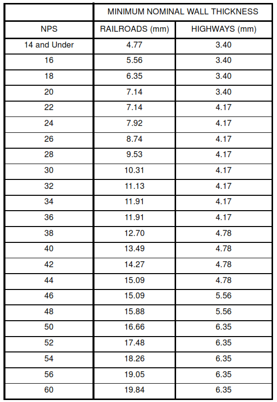
7.3 Standard Minimum Casing Thickness
The minimum nominal wall thicknesses for steel casings are shown in Table I.
Table I Steel Casing Wall Thickness
7.4 Seal Welded Casing
Sealed casings are required for lines under the following conditions.
7.4.1 Fully Restrained
Steel pipelines in hydrocarbon service, that are fully restrained, and the pipeline operates at a hoop stress
greater than 50 percent of SMYS
7.4.2 Groundwater
When groundwater can be within 450 mm below the bottom of the casing.
7.4.3 Method
The ends of the casing shall be seal welded to the main line by the use of split reducers. The reducers
shall be split with longitudinal seams suitable for butt welding, with a full penetration weld. The large end
shall be butt welded to the casing, and fillet welded to the carrier pipe at the small ends.
7.5 Flexible Casing Seals
7.5.1 End Seals
Casing ends shall be sealed with flexible non-metallic material to keep out soil, debris and water.
7.5.2 Criteria
The flexible casing end seals shall be able to accommodate the maximum axial movement of the carrier
pipe without being torn or cut.
7.5.3 UV Protection
The flexible material shall be resistant to ultraviolet light.
7.5.4 Internal Support
When the pipe deflection inside of the sleeve is calculated to be in excess of 10 mm, support shall be
provided for the carrier pipe.
7.6 Application of End Seals
The entire space between the casing and carrier pipe shall be clean and dry when the seals are installed.
7.7 Electrical Isolation
7.7.1 Steel casing shall generally be electrically isolated from the metallic carrier pipe.
7.7.2 Electrical isolation is accomplished by the use of means of non conducting supports or insulators
installed at regular intervals.
7.7.3 Double insulators are required at each end of the casing. The first insulator shall be within 300 mm of
the casing end.
7.7.4 Seal welded casings cannot be isolated.
8. Corrosion Protection
8.1 Casing Coatings
The external surface of steel casing and casing to be thrust bored shall be coated in accordance with SES P12-S01.
8.2 Pipe Inside Casings
Steel carrier pipe inside casing with flexible end seals shall be coated with fusion bonded epoxy. The girth
welds shall have heat-shrink sleeves as a minimum. The coating shall be holiday tested immediately before insertion into the casing, to ensure the integrity of the coating.
8.3 Concrete Casing
8.3.1 Steel pipe encased in concrete shall be coated or protected with heat-shrink sleeves.
8.3.2 An alternative is to provide welded sleeves extending beyond the concrete to approximately 300 mm
inside the concrete.
8.4 Cathodic Protection
When required, cathodic protection shall be in accordance with SES E29-C01.
a. Casings welded to the carrier pipe are considered part of the pipeline.
b. When the casing is electrically isolated from the carrier pipe, the casing is protected by a
separate dedicated Cathodic Protection, in accordance with E29-C01.
9. Installation
9.1 Design
The design shall include:
a. Drawings
b. Construction specifications covering the procedure for installation
c. Instructions for a temporary bypass, if necessary
d. Protection of the pipeline
e. Protection of the road or the railroad.
9.2 Backfill
Backfill shall be free of material that may damage coatings of steel casing or carrier pipe in accordance
with SES P13-C01. Backfill shall be placed in layers of 300 mm or less and compacted to a density
matching the surrounding soil.
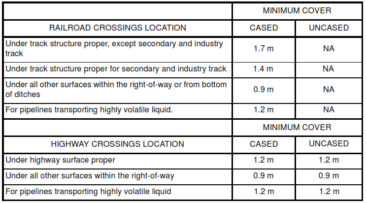
9.3 Minimum Cover
The minimum cover over carrier pipe or steel casing shall be in accordance with Table
II
, unless otherwise
specified by the Saudi Arabian Government.
a. Minimum cover for railroads is measured from the top of the casing pipe to the base of the rail.
b. Minimum cover for highways is measured from the top of the pipe to the top of the ground
surface. Table II Minimum Cover For Pipeline Crossings Under Railroads And Highways
9.4 Uncased Plastic Piping
The bedding, backfill, and minimum cover over plastic and reinforced thermosetting resin carrier pipe shall
be in accordance with SES P13-C05.
9.5 Surface Restoration
All road pavement and sub-base shall be restored. The surface shall be compacted and finished flush with
the adjoining pavement.
9.6 Pipeline Anchors
When the buried length of an uncased crossing is not long enough to provide sufficient friction force,
additional external anchoring is required.
9.7 Pipeline Lowering
Generally, lowering a pipeline for road crossing is prohibited. The pocket formed may cause the
acceleration of internal corrosion. Lowering is acceptable, with approval, for oil flowlines, test lines and
water lines NPS 24 and smaller.
10. Testing and Inspection
10.1 Carrier Pipe
The Carrier pipe is part of the pipeline, and shall be installed, or modified in accordance with the standards
that apply to the pipeline.
10.2 Isolation testing
The electrical isolation of the carrier and casing shall be proven with testing. This test is to be made after
installation of a cased crossing with non-metallic casing seals.
10.3 Seal Welded casing
The integrity of the seal of the welds of casings that are seal welded shall be tested with air at 20 to 35 kPa
and soap suds or other suitable bubble detecting solution.