This article is about Main Wind-Force Resisting Systems for Structures Other Than Enclosed Buildings and all calculation of MWFRS.
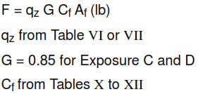
Force coefficients (Cf), in Table X apply to flat-sided members. The specified force coefficients are for towers with structural angles or similar flat-sided members. Design wind forces (F) for structures with a height/least horizontal dimension of ≤ 4 and f ≥ 1.0 cycle/second can be calculated using the following equation:
Af projected area normal to wind except where Cf is given for the surface area.
MWFRS for Structures Other Than Enclosed Buildings
In the calculation of design wind forces for components and cladding for buildings, the algebraic sum of the pressures acting on opposite faces shall be taken into account.
Minimum design wind forces. The wind load used in the design of a main wind-force resisting system shall not be less than 10 lb/ft2 multiplied by the area of the building or structure projected on a vertical plane normal to the wind direction. The design pressure for components and cladding shall not be
less than 10 lb/ft2. The design force for open buildings and other structures shall not be less than 10 lb/ft² multiplied by the area Af.
Table X – Force Coefficients for Trussed Towers, Cf

Note:
1. ε is the ratio of solid area to gross area of one tower face for the segment under consideration.
2. For tower with round members, the design wind force shall be determined using the force coefficient determined in Table X multiplied by the factor (0.51ε² + 0.57), but not >1.0, when determining wind forces on such members.
3. Wind forces shall be applied in the directions resulting in maximum member forces and reactions. For tower with square cross-sections, wind forces shall be multiplied by the factor (1.0 + 0.75ε ) but not >1.2 when the wind is directed along a tower diagonal.
4. For triangular section towers, the design wind forces shall be assumed to act normal to a tower face.
5. For all wind directions considered, the area Af consistent with the specified force coefficients shall be the solid area of a tower face projected on the plane of that face for the tower segment under consideration.
Table XI – Force Coefficients For Open Signs and Lattice Framework, Cf

Notes:
D = Diameter of a typical round member, m (ft).
z = Velocity pressure evaluated at height Z above ground, N/m² (lb/ft²) .
Additional Notes:
1. Signs with openings comprising 30 percent or more of the gross area are classified as open signs.
2. The calculation of design wind forces shall be based upon the area of all exposed members and elements projected on a plane normal to the wind direction. Forces shall be assumed to act parallel to the wind direction.
3. The area Af consistent with these force coefficients is the solid area projected normal to the wind direction.
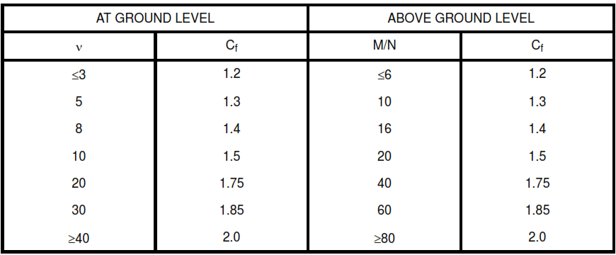
TABLE XII – Force Coefficients for Solid Signs, Cf

Notes:
ϒ= Ratio of height to width
M = Larger dimension of sign, m (ft)
N = Smaller dimension of sign, m (ft)
Additional Notes:
1. Signs with openings comprising less than 30 percent of the gross area are classified as solid signs. Signs for which the distance from the ground to the bottom edge is less than 0.25 times the vertical distance shall be considered to be at the ground level.
2. To allow for both normal and oblique wind directions, two cases shall be considered:
(i) Resultant force acts normal to the face of the sign on a vertical line passing through the geometric center.
(ii) Resultant force acts normal to the face of a sign at a distance from a vertical line passing through the geometric center equal to 0.2 times the average width of the sign.
