This Article is for design, manufacture, testing of low voltage, metal-enclosed power circuit breaker switchgear for indoor installations in unclassified areas. Main keywords for this article are NEC Low Voltage Switchgear Design Requirement, power circuit breaker switchgear, Metal-Enclosed Switchgear, Potential Transformers, Current Transformers.
References
American National Standards Institute / Institute of Electrical and Electronic Engineers (ANSI/IEEE)
C37.13 Standard for Definite Purpose Switching Devices for Use in Metal Enclosed Low-Voltage Power Circuit Breaker Switchgear
C37.16 Preferred Rating, Related Requirements, and Application Recommendations for Low- Voltage AC (635V and below ) and DC (3200V and below) Power Circuit Breakers
C37.17 Trip Devices of AC and General Purpose DC Low Voltage Power Circuit Breakers
C37.20.1 Metal Enclosed Low Voltage Power Circuit Breaker Switchgear
C37.50 Test Procedure for Low-Voltage AC Power Circuit Breakers Used in Enclosures C57.13 Requirements for Instrument Transformer
National Electrical Manufacturers Association (NEMA)
SG 5 Power Switchgear Assemblies
Standard Publication No.ST 1
National Fire Protection Association (NFPA)
70 National Electrical Code (NEC)
Underwriters Laboratories (UL)
1558 Metal-Enclosed Low Voltage Power Circuit Breaker Switchgear
Definitions
For the purpose of understanding this specification, the following definitions apply.
Auxiliary Compartment. The portion of the switchgear assembly assigned for housing auxiliary equipment, for example potential transformers, control power transformers, or other miscellaneous devices.
Circuit Breaker. A device capable of opening and closing the power line feeder to an electrical system manually or automatically. It opens the circuit automatically at predetermined values of over current or fault current by circuit protection relays, without damage to the mechanism or the current-carrying portion of the device. The basic function of this device is to open or close the circuit under normal and abnormal conditions.
Continuous Current Rating. The rated current of metal-enclosed switchgear is the maximum current in rms amperes at rated frequency which can be carried continuously by the primary circuit components, including buses and connections.
Ground and Test Device. A term applied to a switchgear assembly accessory device which can be inserted in place of a draw out circuit breaker for the purpose of (1) grounding the main bus and external circuits connected to the switchgear assembly and (2) primary circuit testing.
Instrument Transformers. Instrument transformers provide power to protective relays in low voltage systems, and are of two types: voltage transformers for use in voltage measurement, and current transformers for use in current measurement. These transformers have two primary functions. Firstly, they serve to reduce the large value of rated primary circuit voltages and current encountered in modern power circuits to a common secondary base, thus permitting standardization of meters, relays or other measuring devices. These secondary values are usually 120 V and 5 A. Secondly, they provide insulation between primary and secondary circuits,
thus protecting meters and devices from dangerously high voltages.
Rated Maximum Voltage. The rated maximum voltage of metal-enclosed switchgear is the highest rms voltage for which the equipment is designed, and is the upper limit of operation.
Stored-Energy Operation. Circuit breaker operation by means of energy stored in the mechanism itself prior to the completion of the operation, and sufficient to complete it under predetermined conditions.
Switchgear. A general term for a design which includes all the equipment required to control an individual circuit. This interrupting device, in combination with the associated controls and metering, provides protection to the cables and equipment. It is primarily used in distribution of electric power for various voltage levels.
NEC Low Voltage Switchgear Design Requirement
Switchgear designed for facilities shall conform to ANSI/IEEE C37.20.1, NEMA SG 5 and UL 1558.
Switchgear Ratings
Voltage Ratings – The rated connected voltage shall be 480 Volts, 3-phase, 3 wire.
Frequency Rating – Rated voltage and current for switchgear shall be based on 60 Hz.
Rated Short-Time Current and Rated Short-Circuit Current – The rated short time current of the metal-enclosed switchgear is the designated limit of available current at which it shall be required to withstand its short-time current duty cycle as specified in ANSI/IEEE C37.20.1, section 4.4.3 and 4.4.4.
Metal-Enclosed Switchgear
- Live parts shall be completely enclosed within grounded metal enclosures.
- Secondary control devices and wiring shall be isolated from the high voltage primary devices by grounded metal barriers, except for certain runs of the secondary wiring where barriers are impractical.
- Circuit breakers shall be removable, equipped with self coupling primary and secondary disconnecting contacts, and arranged with the disconnecting means to physically move between the connected and disconnected positions.
- Major primary circuit components shall be isolated by grounded metal barriers.
- Buses, joints and connections shall be insulated throughout the equipment.
- Interlocking shall be provided, for correct sequential operation.
Metal-Enclosed Switchgear Application
- Metal-enclosed switchgear assembly shall conform to ANSI/IEEE C37.20.1 and shall include draw out type circuit breaker assemblies, buses, fuses and other protective devices, controls, metering and instrumentation.
Metal-Enclosed Switchgear Construction
- Switchgear vertical sections shall be NEMA Type 1, free standing, completely factory assembled, wired, tested, steel construction, with doors and access panels of sufficient size to give full access to all components. Adjacent vertical sections and individual compartments shall be isolated from each other by means of sheet steel barriers. The vertical sections shall be bolted together into an enclosed dead-front assembly mounted on an integral base frame. Vertical sections of the switchgear assembly shall share a common horizontal main bus and a common ground bus running the length of the switchgear line up. The switchgear shall not be configured in a back to back arrangement. The incoming or tie power circuit breaker shall be installed in a single vertical section unless otherwise specified in SES E08-X01.
- Future Expansion. A ‘spare’ switchgear shall be arranged for future expansion, and the enclosures shall be of modular design to permit safe and easy installation of additional units. These units shall include, but not be limited to, such items as predrilled buses, terminal blocks for secondary wiring, and removable enclosure end covers secured by captive hardware on the structure. Enclosure for the future shall be completely equipped to contain breaker stabs, current transformers, bus bars, wiring, test block, relays and circuit breaker to make an operating feeder, as specified on the one line diagram.
- Space Locations. A space location shall be a complete vertical section and shall be similar to a ‘spare’ except that the main circuit breaker shall not be installed.
- There shall be a minimum of one ‘spare’ and ‘space’ location connected to every bus as specified on the one line diagram.
Power Circuit Breaker
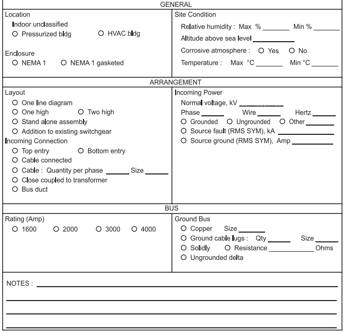
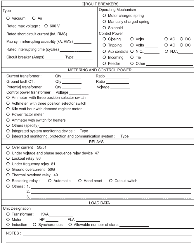
Circuit breakers shall be 3 pole, air break, draw out, electrically and manually operated, rated, manufactured and tested to conform ANSI/IEEE C37.13, C37.16, C37.17 and C.37.50. The breaker shall be fully capable to withstand the short circuit current as specified in above data sheet.
- Breaker Interlocks
Mechanical interlocks shall be provided to make it impossible for a closed circuit breaker to be withdrawn from, or inserted into, the connected position. It shall not be possible to operate a circuit breaker when it is between the connected and test positions. A mechanical device shall be provided to release the energy stored in the
closing springs before a circuit breaker is removed from the cubicle. - Breaker Padlocking
Provision for padlocking circuit breakers in the test or disconnected position shall be provided. Padlocking shall not interfere with the operation of the breaker or its mechanism. When padlocked in the disconnected position, the breaker shall either be not removable from the compartment, or, the access to the racking mechanism shall be
effectively prohibited by the padlock. - Dead-Front Construction
Circuit breakers shall be dead-front construction, equipped with an integral steel-front panel. The breaker assembly shall have full travel alignment guides to position the breaker in the enclosure for entering or pull out. The racking system for the breaker shall have a position indicator – full in, full out and test position. - Breaker Operating Mechanism
whether each circuit breaker shall have a stored- energy type electrically operating mechanism with a spring charging motor or manually operating mechanism. The shunt trip coil shall operate on direct current (dc), with the voltage rating. Each circuit breaker shall be electrically and mechanically trip-free. The closing circuit shall be arranged to preclude repetitive operation during fault conditions if the circuit breaker control switch is held in the close position. Upon loss of control power, it shall be possible to manually recharge the stored energy mechanism by use of a single ratchet wrench or operating lever as specified on reference single line diagram. - Breaker Auxiliary Contacts
Circuit breakers shall be equipped with auxiliary contacts for interlocking with control circuits, indicating lights and auxiliary relays. Auxiliary switches in the breaker and instrument compartment shall be breaker-operated as follows:
a. Each breaker shall be equipped with at least 2 N.O. and 2 N.C. electrically separate breaker auxiliary contacts operated by the breaker and wired from the breaker to terminal blocks. These contacts shall be in addition to those required for circuit breaker operation.
b. Each breaker compartment shall be equipped with a minimum of 2 N.O. and 2 N.C. electrically separate mechanism-operated type (MOC) auxiliary switch contacts. These contacts shall operate only in the connected and test positions.
c. An alarm switch shall be provided for an auto-trip by overcurrent solid state trip unit and shall not be operated by other trips
- Interchangeability
Circuit breakers of the same rating shall be interchangeable and interlocked with the breaker cubicle to prevent insertion of a breaker with a lower continuous or interrupting rating into a higher rated compartment.
Switchgear Main Bus
Main Bus Ratings
- Continuous current rating of the main bus shall match that of the switchgear.
- Main bus shall be designed and rated for the full ampere capacity specified, and shall not be tapered for the purpose of reducing current densities.
- Main bus shall be copper with silver plated joints, and shall have epoxy, flameretardant and rack-resistant insulation. Main bus insulators between units shall be flame-retardant, track-resistant, glass polyester for 1 kV class. Switchgear shall be constructed so that all buses, bus supports and connections shall withstand stresses produced by currents equal to the momentary ratings of the circuit breakers. A set of insulated copper main buses with ratings as per IEEE C37.20.1 shall be provided, which shall have provisions for future extension. Bus joints shall be plated, bolted and insulated with easily installed boots. Bus shall be braced to withstand short circuit current available at the location of the switchgear but not less than 42,000 symmetrical amperes at rated maximum voltage 600 V ac for a period not less than 4 cycles. The temperature rise of the bus and connections shall be in accordance with ANSI/IEEE C37.20.1, and documented by design tests.
- Main bus shall extend the full length of the assembly and shall be drilled at both ends for the addition of splice plates to extend the bus in either direction for future expansion.
- Vertical Bus. The continuous current rating of the vertical bus shall be no lower than to the frame size of the LV power circuit breaker.
Switchgear Ground Bus
A 6.35 mm by 50.8 mm (minimum) copper ground bus shall be provided over the entire length of the assembly, with provisions for extensions at either end for future
expansion. Provisions shall also be made to terminate a 120 mm2 copper ground system cable at each end. Ground bus shall be routed at the rear of the assembly.
High Resistance Grounding
A high resistance grounding detecting and alarming cabinet shall be furnished for each low voltage switchgear. The high resistance grounding system shall consist of a neutral-connected single-phase distribution transformer, low voltage grounding resistor, and ground sensing relay. The grounding resistor shall include a center tap and a pulsing contactor to allow troubleshooting upon fault sensing.
Control Power
Standard control voltage for low voltage switchgear installations shall be 125 V dc usually derived from station batteries located near the switchgear in the substation building. This shall be used for protective device control and operation. In addition to these requirements, 120 V ac will be required for switchgear interiors equipped with lighting, space heaters and convenience outlets from power panels in sub station buildings.
Control Power Wiring
Minimum wire size for control power circuit shall be 2.5 mm2 (14 AWG) stranded copper, 600 V, rated at 90 oC or greater, and shall conform to NFPA 70. The control power wiring shall be isolated from the low voltage primary side wiring by grounded metal barriers. Each wire shall be identified with heat-shrinkable snap-on permanently marked numbers, corresponding to the connection points in the switchgear control systems wiring diagrams.
Potential Transformers (PT)
- Potential transformers shall be provided as required, to power instruments, metering, and relaying, as shown on the single line diagram specific to the switchgear. The manufacturer of the equipment shall be responsible for checking that burdens conform to ANSI/IEEE C57.13. Basic Impulse Insulation Level (BIL) shall be coordinated with that of the switchgear.
- Potential transformers shall be fixed type, with primary and secondary side current limiting dual element fuse protection, and secondary MCP protection.
- Minimum wire size for the potential transformer secondary circuit shall be 2.5 mm (14 AWG) stranded copper, 600 V, rated at 90 °C.
Current Transformers (CT)
- Current transformers shall be provided in the application of instruments, meters, and relaying as shown on the single line diagram specific to the switchgear. The manufacturer of the equipment shall be responsible for checking burdens to be in compliance with ANSI/IEEE C57.13, and the BIL shall be coordinated with that of the switchgear.
- Current transformers shall be insulated for the full voltage rating of the switchgear, and shall be mechanically rated to withstand the maximum short circuit momentary rating of the switchgear.
- Primary CT current rating shall be the nearest standard rating equal to not less than 125 percent of the normal primary current in the circuit.
- Minimum wire size for current transformer secondary circuits shall be 2.5 mm (14 AWG) stranded copper, 600 V, rated at 90 0C.
- When required by the specification, shorting links shall be provided on the CT’s terminal block.
Control Power Transformers (CPT)
- Control power transformer shall be in accordance with NEMA ST 1.
- Current limiting fuses shall be provided on CPT primary side.
- QCPT secondary side shall be protected with overcurrent devices.
- Instrument transformer shall be provided with ratios to match the input requirements of the solid state devices and shall conform to IEEE C57.13.
Safety Devices
It is critical to limit personnel exposure to shock hazard and the results of internal faults within the switchgear. For these reasons the following general guidelines shall be followed in specifying safety features to be incorporated into the metal-clad switchgear:
a. Positive mechanical interlocks
b. Complete protection shall be provided against contact with live parts
c. The circuit breaker trucks shall be fully integrated into the interlock system
d. Partitions and barriers shall be provided where required, to prevent the spread of faults
e. Enclosures shall have been arc-fault tested, and be capable of withstanding the maximum internal pressure that may be generated by a fault in theswitchgear
f. Circuit breakers shall be capable of being line tested while still being inserted
Auxiliary Compartment
- Auxiliary compartment shall be sheet-steel enclosures similar to circuit breaker cells, but without provisions for the circuit breaker. They shall be used to house voltage and control power transformers, fuses and other auxiliary devices. Drawout trays may be included for the mounting of the transformers.
- Front door panel of the auxiliary compartment may be used to mount meters, switches, alarm relays to the annunciator panel, or other types of instrumentation.
Voltage Rating and Insulation Withstand
Rated maximum voltages and corresponding insulation level withstand capability for ac LV switchgear and metal enclosed bus are listed in Table I.
Primary Termination Compartment
Primary termination compartment shall be located at the rear of the switchgear and shall be separated from the other compartments by metal barriers.
- Cable Terminations
If the primary connection is to be made by cable, the size and number per phase of crimp or compression type cable lugs shall be provided, based on the size and type of cable to be used. Load side of circuit breaker shall have provisions for terminating the required number of cables. - Busduct Termination
If the primary connection is to be made by busduct, the proper provisions for connection to a bar-type busduct, rated as specified in Above data sheet, shall be installed at the top of the compartment.


