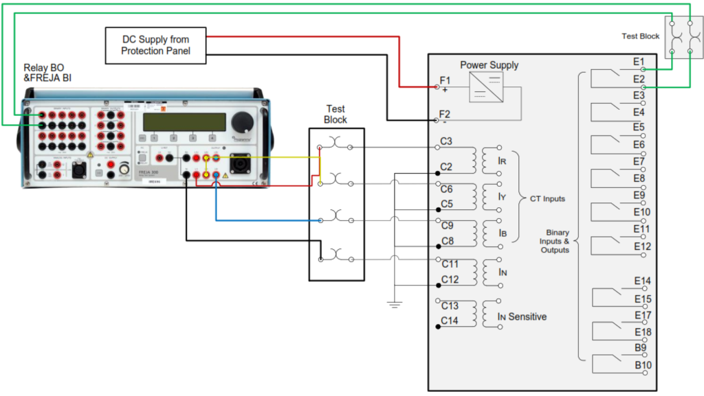
Testing overcurrent, undercurrent, and earth fault relays is crucial for ensuring the protection and reliability of electrical systems. This article is to guide the responsible persons in conducting Overcurrent, Under Current and Earth Fault Relays Test.
Test Equipment: Secondary Injection test kits; Multimeter; Digital Timer.
Safety Precautions: The following Safety precautions shall be taken in consideration prior, during and after conducting the test measurements.
- Safety tagging shall be implemented.
- Isolate the Area by Safety Warning Tape.
- Keep a Safe Distance from the device being tested.
- Wear Appropriate Personal Protective Equipment (PPE) Prior to starting any testing activity.
- Implementation of Proper Grounding.

Perform General Visual Inspection as per Works Instruction.
- Perform the tests required as per the following test connection for injection of secondary Current values to the relay:

Overcurrent Relay Test.
To ensure the relay operates correctly when the current exceeds the predefined threshold.
3.1 Measure and Record the relay’s Pick up Current and contact timing for L1 to L2 (Phase R), L2 to L3 (Phase Y), L3 to L1 (Phase B), by gradually increasing the injected current until such time the pick-up current is reached. Repeat step for different curves (NI, EI, LTI, DT,..etc) as per requirement or as indicated in the Test form.
3.2 Measure and Record the relay’s Drop off Current and contact timing for L1 to L2 (Phase R), L2 to L3(Phase Y), L3 to L1(Phase B), by gradually decreasing the injected current until such time the drop-off current is reached. Repeat step for different curves (NI, EI, LTI, DT,..etc) as per requirement or as indicated in the Test form.
3.3 Calculate the Reset Ratio with the formula:
Reset Ratio = ( Idrop-off / Ipick-up ) x 100%
Under Current Relay Test.
To ensure the relay operates correctly when the current falls below the predefined threshold.
4.1 Measure and Record the relay’s Pick up Current and contact timing for L1 to L2 (Phase R), L2 to L3 (Phase Y), L3 to L1 (Phase B), by gradually increasing the injected current until such time the pick-up current is reached. Repeat step for different curves (NI, EI, LTI, DT,..etc) as per requirement or as indicated in the Test form.
4.2 Measure and Record the relay’s Drop off Current and contact timing for L1 to L2 (Phase R), L2 to L3 (Phase Y), L3 to L1 (Phase B), by gradually decreasing the injected current until such time the drop-off current is reached. Repeat step for different curves (NI, EI, LTI, DT,..etc) as per requirement or as indicated in the Test form.
4.3 Calculate the Reset Ratio with the formula:
Reset Ratio = ( Idrop-off / Ipick-up ) x 100%
Earth Fault Relay Test.
To ensure the relay operates correctly when a ground fault occurs.
5.1 Measure and Record the relay’s Pick up Current and contact timing for L1 to N (Phase RN), L2 to N (Phase YN), L3 to N (Phase BN), by gradually increasing the injected current until such time the pick-up current is reached. Repeat step for different curves (NI, EI, LTI, DT,..etc) as per requirement or as indicated in the Test form.
5.2 Measure and Record the relay’s Drop off Current and contact timing for L1 to N (Phase RN), L2 to N(Phase YN), L3 to N (Phase BN)),by gradually decreasing the injected current until such time the drop-off current is reached. Repeat step for different curves (NI, EI, LTI, DT,..etc) as per requirement or as indicated in the Test form.
Calculate the Reset Ratio with the formula:
Reset Ratio = ( Idrop-off / Ipick-up ) x 100%