1.0 Pretest Inspection.
2.0 No load test Procedure.
3.0 Load Test Procedure at 100% Safe Working Load.
4.0 Overload Test Procedure at 125% Safe Working Load.
5.0 Test report.
6.0 Reference standards.
7.0 List of safety devices to be checked.
8.0 List of items required for load test.
1.0 Pretest Inspection
1.1 For overhead crane it is necessary to ensure that the Runway and supporting
structure are thoroughly examined. A visual examination of the runway within the test area
should be made prior to commencing the test to ensure their suitability to withstand the test loads
1.2 Review the crane runway dimensions survey report and building clearances.
1.3 Insulation tests : After completion of erection and before connection of the power supply ,the
insulation of the electrical systems shall be tested. The voltage used shall be a D.C. voltage of
not less than twice the rated voltage of the system concerned and all phases shall be checked
for each crane motion or system.
The insulation resistance of the systems tested shall be not less than 0.5 MO.
If a reading less than 0.5 MO is obtained ,the systems under test shall be subdivided. Each
subdivision shall then show a reading of not less than 0.5 MO
1.4 Earth Continuity : Earth continuity of the equipment shall be checked to ensure that at no point the
reading is greater than 0.5 0.
1.5 The orientation of the crane, location of the Power line/Main switch and the height of control
pendent for convenience of operation shall be checked with reference to the GA drawing.
2.0 No load test Procedure
2.1 Before the application of any load, a through examination of the crane by a functional test
with no load to be carried out to ensure the correct operation of Controls, switches, contactors,
relays and other devices. The operation and correct adjustments of the brakes and limit switches
should be checked and tests carried out to ensure that primary safety and emergency
systems are operating correctly.
3.0 Load Test Procedure at 100% Safe Working Load
3.1 Deflection test:
At the start of the test the crane should be positioned over a supporting stanchion or column of the
Runway beam in order to minimize the influence of Runway beam deflection in the girder deflection readings. The hoist to be positioned at centre of the crane span.
Using a suitable measuring device (Scale) note down the Girder level (Reading-1).
The safe working load should now be raised ~0,3m height. Measure and note down the Girder level (Reading-2).
The difference between the Reading-1 & 2 is the deflection of the Girder.
The maximum deflection of the main bridge with the hoist and safe working load at the centre of span should not exceed 1/900 of the span.
e.g. For a crane with a span of 24 Meters the following calculation would apply.
Maximum deflection = 24,000 / 900 = 26.6 mm
Note: If the allowable deflection is different for a specific project, the same has to be calculated based on the project specification.
3.2 The safe working load should now be raised ~1,5 to 2m height to ensure that each tooth of the
Hoist train of gears is subjected to the load. The load should be held in this position for 10 minutes to check the brake.
3.3 The load should then be raised by a further ~200mm and then lowered to check the ability of the Hoist to lift the suspended load.
3.4 The load should then be traversed towards one side for 2M both right and left so that each tooth
of the cross travel train gears is subjected to the load. Move the load towards either side of the runway to the hook approach position and then Crane should be traveled along the Runway for ~2m both forward & backward. Then the trolley should be returned to its original lift position.
3.5 Brake Test: Check whether the Hoist brake arrest the motion & hold the load when the power is
cut off (i.e. Push Button is released). Check whether the Travel/Traverse brakes arrest the
respective motion & bring the fully loaded Trolley/ Crane to rest without shock at high speed.
3.6 Speed check: Hoisting, Traversing & Travelling speeds to be measured using stop watch.
Travel distance = d (m) => 0.5m for Hoist & 2 to 4 m for Trolley & Crane
Time taken = t (sec)
=> Speed=d*60/t => The speeds should be ±10% of the Rated speed.
Do this procedure for hoist / trolley / crane for both slow & fast speeds. Allow for acceleration to reach full speed before taking initial reading.
3.7 Over load Device check: The working load to be increased by 25% & Hoisting to be performed. Due to the overload, the overload device should trip.
4.0 Overload Test Procedure at 125% Safe Working Load
4.1 Bypass the overload device as stipulated in the O&M instructions. The working load should be increased by 25% to form a test load.
e.g. : Over load for a 10T crane = 10T + 25% of 10T = 12,5T
The load shall be moved in all the directions so that each train of gears is subjected to the load as ‘
elaborated in above section. This test is only to check the stability of the crane and hence no
measurement is required to be taken.
4.2 During the overload test the crane should be capable of handling the overload and the brakes
on each motion should be tested to ensure that they function effectively. The traverse and
travel brakes should also function effectively with the overload (Refer Clause 3.5).
4.3 During the overload test the crane should only be operated at speeds appropriate to the safe
control of the load.
4.4 On completion of the tests, a further thorough examination of the crane should be carried out and
overload protection devices should be reset and their correct operation verified.
Note: This may include inspection for cracks, permanent deformation, gear teeth damage.
5.0 Test report
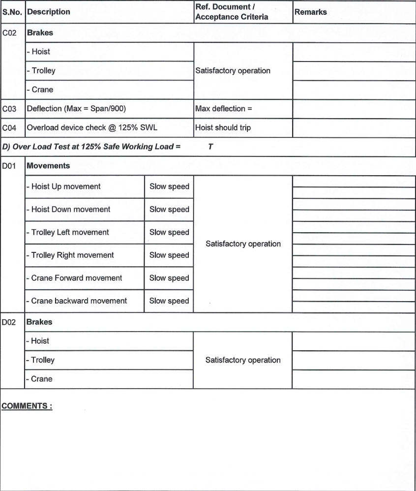
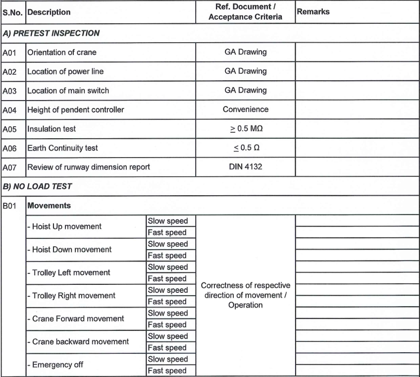
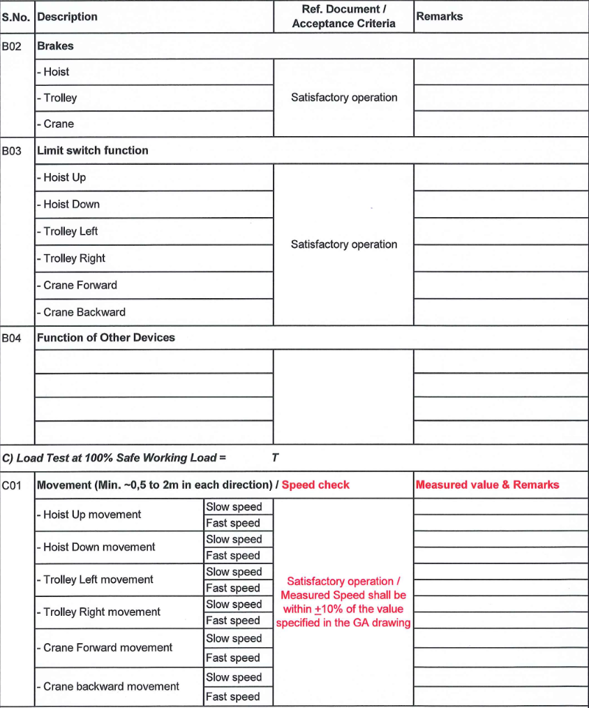
5.1 Typical Test report is attached which may be used to record the results of the testing.
When the procedure has been satisfactorily completed, the testing engineer should issue a
Test certificate as required.
6.0) Reference standards
6.1 FEM 9.811 & BS 466
7.0 List of safety devices to be checked:
1. Hoist overload device
2. Hoist/ Trolley / Bridge brakes
3. Hoist up/down Limit switch
4. Trolley Limit switch
5. Bridge Limit switch
8.0 List of items required for load test :
1. Certified test loads OR Test loads & Load cell.
2. Suitable slings & shackles.
3. Measuring device to check girder deflection.
4. Stop watch for Speed check.
5. Megger.
6. Ammeter & Multi meter (to be used just in case of electrical trouble) if it is necessary to make mechanical alterations to the Equipment to meet the specified operating criteria, the test shall be repeated after the corrections have been made.
OVERHEAD CRANE SITE TEST REPORT FORMAT


