- Introduction
- Definitions
- Overview
3.1 Terminal Markings
3.2 Polarity
3.3 Angular Displacement
3.4 Voltage Diagram
- International Conventions
4.1 ANSI
4.2 IEC - Paralleling Mismatched Transformers
5.1 ANSI
5.2 IEC
1. Introduction Paralleling Mismatched Transformers
The purpose of this Article is to provide guidance of how to manipulate the secondary phase conductors of three phase transformers with different vector groupings to allow them to be safely paralleled.
2 Definitions
3. Overview Paralleling Mismatched Transformers
It is common in industry that transformer secondaries must be operated in parallel. This parallel operation may be either temporarily, as is the case for a Normally-Open secondary selective scheme or permanently in the case of a Normally-Closed scheme.
For this parallel operation to be possible, several factors must be the same between the transformers being paralleled, for example:
– phase voltages.
– frequency.
– phase rotation
– polarity
Long-term paralleling requires other factors be matched (e.g., impedance, power rating). These will not discuss since the focus of this article is to only to provide guidance on compensating for angular displacement and polarity mismatches.
Phase voltage is easy to match and in general the transformers being paralleled are always connected to the same frequency. Matching the phase rotation and polarity can be a problem if the winding connection configuration on the primary and secondary of the transformers are not identical.
This article provides the guidelines on how to manipulate the transformer and secondary phase conductor connections to achieve a matched vector grouping and phase shift on the secondaries of the transformers.
3.1 Terminal Markings
Transformer windings are marked to show polarity and also to designate high and low voltage. For the purpose of terminal marking “primary” and “secondary” are meaningless because these terms depend on the input and output terminal connections.
In addition, terminals are numbered to indicate direction of induced voltage (i.e., polarity). Specific marking conventions are different depending upon whether the transformers are built to IEC or ANI standards. See Section 4 for a description of these differences.
3.2 Polarity
Polarity is a designation of the relative instantaneous directions of the currents in the transformer leads. Primary and secondary leads have the same polarity when, at a given instant, the current enters the primary lead and leaves the secondary lead in the same direction as though the two leads formed a continuous circuit. See Figures 1 and 2 for a visual representation of this explanation, using a single phase transformer for clarity. Figure 1 shows “subtractive polarity” and Figure 2 “additive polarity”. Note that difference between the two is only the winding direction around the core of one of the windings.
Figure 1 Figure 2
Subtractive Polarity Additive Polarity


This polarity is usually designated by means of a voltage vector diagram showing the angular displacements of the windings and a sketch showing the lead markings. The vectors represent the induced voltages with the counterclockwise direction of rotation. The vector that represents any phase voltage of a given winding is drawn parallel to the corresponding phase voltage of any other winding under consideration. See Figures 3 and 4.
3.3 Angular Displacement
The main three-phase connections commonly used are wye-delta, delta-wye, delta-delta and wye-wye. The below figure shows a wye-delta connected transformer with subtractive polarity (the HV and LV windings are wound the
same direction on the core) and a 30 degree angular displacement.
Figure 3 – Wye-Delta, Subtractive Polarity, 30 Degrees Angular Displacement

“Phase rotation” refers to a perfectly definite order in which the leads connections are considered. In the above diagram, phase rotation is counterclockwise in the order H1-H2-H3.
Figure 4 – Wye-Delta, Additive Polarity, 30 Degrees Angular Displacement

3.4 Voltage Diagram
Voltage diagrams are used to pictorially summarize the angular displacement, connection, and terminal markings.
Note that the voltage diagrams of Figures 3 and 4 are identical even though the transformers are wound differently. This has been compensated for by making the lead lettering different. Different lead lettering is equivalent to
interchanging the leads.
4. International Conventions of Paralleling Mismatched Transformers
There are two industry standards that govern the construction and labeling of power transformers as it relates to the discussion in this ANSI and IEC. Each is slightly different.
4.1 ANSI
Angular displacement:
30 degrees with the low-voltage terminal X1 lagging the high-voltage terminal H1.
Terminal Markings:
High Voltage windings: H1, H2, H3. Low-Voltage windings: X1, X2, X3
Figure 5 – ANSI C57.12.70 extract

4.2 IEC
Angular Displacement
Indicated by phase displacement “clock number”. Conventions are as follows:
– Connection diagram shows the high-voltage winding above the low voltage winding.
– Directions of induced voltages are indicated.
– The high-voltage winding phasor diagram is oriented with phase I positioned at 12 o’clock. The phase I phasor of the low-voltage winding is oriented according to the induced voltage relation which results for the connection shown.
– The phasor rotation is counter-clockwise (giving the sequence I-II-III in the example).
Terminal Markings
High Voltage windings: Y, D, Z. Low-Voltage windings: y, d, z.
Figure 6 – IEC 60076-8 extract Voltage Diagram showing “Clock Sequence”
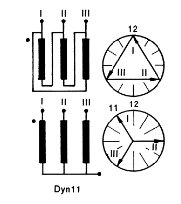
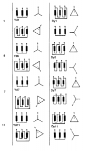
Figure 7 – IEC 60076-8 extract Delta-Wye combinations and clock number
5 Paralleling Mismatched Transformers
As indicated, by interchanging leads, identical voltage diagrams are obtained on wye-delta transformers with different internal arrangements. All wye-delta or delta-wye connections can be reduced to the same diagram by properly selecting the order of the leads. This is not possible with delta-delta or wye-wye connections.
ANSI and IEC standards describe the methodology of manipulating the connections. Because of the different conventions and terminology between the documents, the two standards describe the process differently but the result is the same.
In Figure 10, two sets of delta-wye transformer combinations are shown with two “clock hour numbers” of 1 and 11. They also have an associated “permutation” clock number (e.g. clock number 1 can be 5 by permutation). This means that if the secondary terminals of a trasnformer with clock number 1 were simply renamed by cyclic permutation (II becomes I, III becomes II and I becomes III), then the phase displacement is changed by 120 degrees to clock number 5. Consequently, transformers with connection clock numbers differing by 4 or 8 can be connected in parallel after cyclic permutation of the connections to the line on either side of the transformer (as shown in the diagram on the right-top of Figure 10).
Transformers with clock numbers 1 or 5 can be paralleled with transformers of clock numbers 11 or 7 by reversing the phase sequence on both sides of either transformer.
EXAMPLE: Connecting two delta-wye transformers in parallel. One is 30 degrees lagging, the other is 30 degrees leading. We need to compensate for the 60 degree difference in angular displacement by reconnecting the leads.
IEC: The 30 degrees lagging would be a Dy1 transformer and the 30 degress leading would be a Dy11. The Dy11 angular displacement is 60 degrees different from Dy1 (leading). As indicated in the diagram on the right of Figure 10, this can be compensated by reversing the phases on both the primary and secondary connection.
ANSI: Figure 8 shows the first transformer “a lags A by 30 degrees”. Figure 9 shows the second “a leads A by 30 degrees”. This shows the 60 degree compensation and indicates it was achieved by reversing the phase sequence on both the primary and secondary cconnections. Same result as IEC.
5.1 Paralleling Mismatched Transformers According to ANSI
Figure 8 – ANSI C57.12.70 extract – Lagging Connections

Figure 9 – ANSI C57.12.70 extract – Leading Connections

5.2 Paralleling Mismatched Transformers According to IEC
Figure 10 – IEC 60076-8 extract

