An NR PDCCH is more similar to an LTE ePDCCH than to an LTE PDCCH, with each NR PDCCH being independently processed. Each NR PDCCH has its own DMRS, allowing the NR PDCCH to fully benefit from antenna beamforming.
Before the time-frequency structure of the PDCCH is described, the concepts of CCE, REG, and aggregation level must be explained.
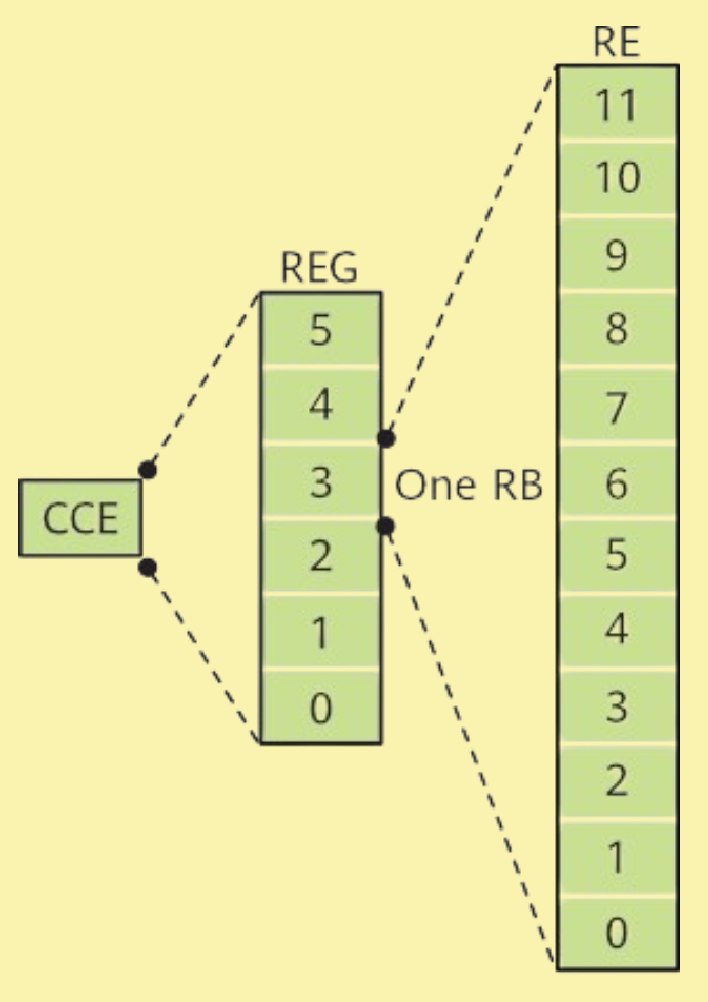
CCE and REG: PDCCH resources are mapped to RBs. As a PDCCH occupies a large number of RBs, REG and CCE have been introduced to simplify the count of resources occupied by the PDCCH. One CCE corresponds to six REGs, and each REG corresponds to one RB, as shown in figure below. CCE is used to describe the resources that can be occupied and actually occupied by the PDCCH. For example, there are a maximum of 45 CCEs (270 RBs) in a symbol when the bandwidth is 100 MHz (273 RBs) and the subcarrier spacing (SCS) is 30 kHz.

Aggregation level: In NR, a PDCCH can use 1, 2, 4, 8, or 16 consecutive CCEs, and these numbers correspond to aggregation levels, as listed in Table below. If the radio channel quality is poor, a high aggregation level is required to ensure the PDCCH transmission quality. The higher the aggregation level, the better the PDCCH demodulation performance.
However, this may waste resources. The gNodeB determines the CCE aggregation level for a PDCCH based on factors such as channel quality. For example, a high CCE aggregation level needs to be selected for the PDCCHs intended for cell-edge UEs (CEUs), ensuring demodulation performance at the cost of more resources, and a low CCE aggregation level can be selected for the PDCCHs intended for cell-center UEs (CCUs), saving time-frequency resources.
| Aggregation Level | Number of CCEs |
|---|---|
| 1 | 1 |
| 2 | 2 |
| 4 | 4 |
| 8 | 8 |
| 16 | 16 |
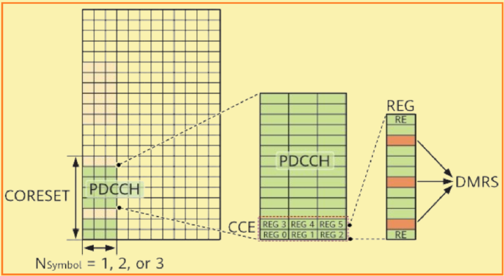
The time-frequency structure of a PDCCH is as follows:
- In the time domain, the first one, two, or three symbols in a slot are occupied.
- In the frequency domain, an entire bandwidth or a parameter-specified bandwidth is occupied.
The time-frequency position of DMRS for PDCCH is fixed at subcarriers 1, 5, and 9 of each REG in the corresponding symbols of the PDCCH. For effective PDCCH demodulation, the DMRS for PDCCH is mapped to one of every four subcarriers in an REG. In other words, the DMRS accounts for one fourth of PDCCH consumption, which is higher than one sixth in LTE. The use of PDCCH-specific DMRSs increases resource consumption by reference signals, but also brings benefits. For example, beamforming can be performed for each UE. PDCCH beamforming, in line with the “beam-centric NR” design concept, improves both the coverage and performance of the NR PDCCH.

Note: The REGs in a CCE are numbered (from 0 to 5) first in the time domain and then in the frequency domain, as defined in the protocol.