1. INTRODUCTION
2. REFERENCE DOCUMENTS
3. GENERAL REQUIREMENT
4. TEST PACKAGE PREPARATION
5. PREPARATION FOR PRESSURE TEST
6. PROCEDURE OF PRESSURE TEST
1. INTRODUCTION
This procedure covers pressure testing of piping system and integral components to assure mechanical soundness and tightness which will be conducted and/or after completion of shop fabrication and field installation work for REFINERY PROJECT. Testing of gravity flow, underground drainage piping, instrument tubing, plumbing system is not included in this procedure.
2. REFERENCE DOCUMENTS
2.1 Project Specifications
S-000-1360-001 : PIPING MATERIAL SPECIFICATION
S-100-1360-001 : LINE DESIGNATION TABLE FOR UNIT J10
S-110-1360-001 : LINE DESIGNATION TABLE FOR UNIT J11
S-120-1360-001 : LINE DESIGNATION TABLE FOR UNIT
J12 S-140-1360-001 : LINE DESIGNATION TABLE FOR UNIT J14
S-000-3160-002 : SPECIFICATION FOR PIPING CONSTRUCTION WORK IN FIELD
S-000-3160-006 : LINE CHECK SCOPE OF WORK
S-000-3160-007 : PIPING INTERNAL CLEANING PROCEDURE
S-000-3160-009 : BOLT TENSIONING PROCEDURE
2.2 ASME (American Society of Mechanical Engineers) Standards
ASME B 31.3 : Process Piping
2.3 Saudi Aramco Standard
SAES-A-004 : General Requirements for Pressure Testing
SAES-A-007 : Hydrostatic Testing Fluids and Lay-Up Procedures
SAES-L-150 : Pressure Testing of Plant Piping and Pipelines
SAES-L-350 : Construction of Plant Piping
SAES-S-070 : Installation of Utility Piping Systems
GI-0002.102 : Pressure Testing Safely
3. GENERAL REQUIREMENT
3.1 General Instruction GI-0002.102 “Pressure Testing Safely” shall be followed during pressure testing
3.2 All newly constructed plant piping shall be subjected to hydrostatic test in accordance with this procedure and reference documents.
3.3 All welded attachments such as pipe supports and hanger lugs etc. shall be made before pressure testing. No welding should be done after hydro / pneumatic testing except for seal welding at test vent / drain.
3.4 For piping systems, that has already passed a successful pressure testing, a second pressure testing is required if it is subjected to new welding activities and post heat treatment (PWHT) is mandated due to these new welds. In case PWHT is not required and only for the following cases second pressure testing is not require;
– Seal welds of threaded connections
– Attachment welds of non-pressure containing parts, such as wear pads.
3.5 If block valves are used for blocking or isolating hydrostatic test sections, the differential pressure across the valve sheet shall not exceed the closure test pressure during the pressure test.
3.6 For all internally coated piping system, the test pressure shall not produce hoop stresses in the pipe that could damage the internal coating. However, it shall not be less than the minimum required by the applicable Code. Deviation to this requirement shall be approved by both the Chairman of the Paints and Coating Standards Committee and the Chairman of the Piping Standards Committee.
3.7 All joints excluding butt welds shall be left uninsulated and unpainted for examination during testing except those joints previously tested in accordance with this procedure. Butt weld joints can be painted prior to testing with condition that the weld repair shall not exceed 7.5% joint basis or 0.4% on linear basis.
3.8 A pressure relief valve shall be provided to protect the piping from the overpressure. Relief valve of adequate capacity set to relieve at 5% above the test pressure shall be installed. The relief valve shall be tested, dated, and tagged within one week prior to the pressure test.
3.9 In addition to the pressure relieving device, a bleed valve shall be provided to protect the piping and equipment from overpressure. The bleed valve shall be readily accessible in case immediate depressurization is required.
3.10 An isolation valve shall be provided between the pressure testing manifold and the system being tested. The isolation valve shall be rated for the manifold test pressure when in the closed position.
3.11 A check valve shall be provided between the pressure testing manifold and pressurizing pump due to easier pressurizing.
3.12 Before employing the pressure testing manifold in the actual system pressure
test, it shall be separately pressure tested to at least 1.2 times the system test
pressure and not less than the discharge pressure of the pump used for the
pressure testing.
3.13 Pressure gauges shall be calibrated before the test. The calibration interval shall not exceed one (1) month. The gauges shall be tagged with the date last calibrated and expire date. Each gauge shall have an identifying mark or number which shall appear on the calibration certificate. All pressure gauges shall have a range such that the test pressure is within 30 to 80% of the full range and their accuracy shall be within 5% of one another. A minimum of two (2) pressure gauges shall be provided for the test system. One pressure gauge shall be on the test manifold and the other(s) on the test system.
3.14 The following treatment shall be taken for pressure test water.
3.14.1 Water quality of intended pressure test water shall be determined well ahead of the actual testing date so that alternative water sources may be identified if the original source water fails to meet requirements.
4. TEST PACKAGE PREPARATION
4.1 Test Package shall be submitted prior to conducting hydrostatic test. The following documentation shall be included in each Test Package.
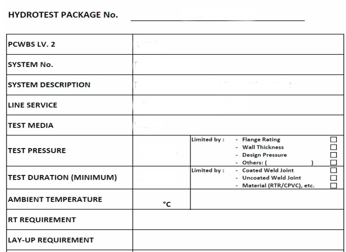
1) Test Package Cover Sheet
This sheet contains the basic information concerning the pressure test including Test Package Number, Test Medium, Test Pressure and Test Duration. Test Pressure shall be approved by Company Engineer. See Attachment-1 Test Package Cover Sheet
2) Test Package Flow Chart (Attachment-2 of SAIC-A-2003)
The signature of interested persons shall be put accordingly. See Attachment-2 Test Package Flow Chart
3) Table of Contents
This sheet is an index of the documents contained within the test package andwill be used for checking off test package contents. See Attachment-3 Table of Contents
4) Drawing Summary Report (P&ID No./ISO Drawing No./Line No.)
See Attachment-4 Drawing Summary Report
5) Pressure Test Diagram using marked up P&ID
Test limits and lines to be tested shall be marked up on the relevant P&IDs.
This sheet covers Hydro Test Diagram.
See Attachment-5 (1/2) Marked Up P&ID
See Attachment-5 (2/2) Marked Up P&ID Symbols
6) SPOOL Erection Drawing
SPOOL Erection Drawing for all of the piping lines associated with the piping pressure test shall be attached. See Attachment-6 SPOOL Erection Drawing
7) Pre-Test Punch List Form (Equivalent of SATR-A-2011)
See Attachment-7 Pre-Test Punch List Form (Equivalent of SATR-A-2011)
8) CMS Welding Summary Sheet (Equivalent of SATR-W-2008)
Weld joint data, welder performance and special process (NDE, PMI, etc) shall be entered on this sheet. See Attachment-8 Welding Summary Sheet (Equivalent of SATR-W-2008)
9) Internal Cleanliness Report (SATR-A-2008)
See Attachemnt-9 Internal Cleanliness Report (SATR-A-2008)
10) Water Chemistry Report (SATR-A-2014)
See Attachment-10 Water Chemistry Report (SATR-A-2014)
11) Test Manifold No. & Capacity
12) Calibration Test Report-Pressure Gauge (SATR-A-2002)
See Attachment-11 Calibration Test Report-Pressure Gauge (SATR-A-2002)
13) Calibration Test Report-Temperature Gauge (SATR-A-2003)
See Attachment-12 Calibration Test Report-Temperature Gauge (SATR-A- 2003)
14) Calibration Test Report-Pressure Recorder (SATR-A-2004)
See Attachment-13 Calibration Test Report-Pressure Recorder (SATR-A-2004)
15) Calibration Test Report-Temperature Recorder (SATR-A-2005)
See Attachment-14 Calibration Test Report-Temperature Recorder (SATR-A2005)
16) Calibration Test Report-Pressure Test Relief Valve (SATR-A-2006)
See Attachment-15 Calibration Test Report-Pressure Test Relief Valve (SATRA-2006)
17) Verify Test Equipment (Safety Assessment) (SAIC-A-2009)
See Attachment-16 Verify Test Equipment (Safety Assessment) (SAIC-A-2009)
18) Pressure Test Report (SATR-A-2001)
See Attachment-17 Pressure Test Report (SATR-A-2001)
19) Test Package Lay-up Report (SATR-A-2009)
See Attachment-18 Test Package Lay-up Report (SATR-A-2009)
4.2 Each test package will have a unique identification number that contains both the PCWBS area reference and the System/Subsystem Code that the test package is associated with.
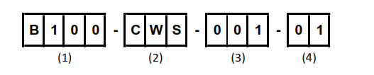
(1) – Level 2 PCWBS Area code where piping is located
(2) – Fluid Code
(3) – Sequential Number starting from 001
(4) – Suffix Number (See below)
In the event, a piping pressure test is subjected to a number of partial test, each partial test will be given the same test package number as the main test but include a suffix. Suffix numbers will be sequential starting from 01.
5. PREPARATION FOR PRESSURE TEST
5.1 Piping shall be thoroughly vented of air during introduction of the test water. High point vents and low point drains to be provided as required and to conform to the relevant line class. All lines shall be checked to ensure entire system can be completely drained after testing.
5.2 Temporary blind flanges and test blinds shall be installed at locations shown on the marked up P&ID Schematics included in the Pressure Test Pack. Test blind shall be of an adequate thickness to withstand the test pressure. Test blind should be lifted and installed by using Flange Jack which is the special jig for safety and easy installation.
5.3 Temporary gaskets shall be installed for pressure test. The temporary gaskets shall be equivalent to permanent gaskets for #600 and higher rating and all RTJ lines.
5.4 For preventing possible deformation of piping due to the weight of test water, temporary supports or other proper means of support shall be provided when necessary. These supports shall not be removed until the system has been fully drained.
5.5 For pressure tests on piping systems with check valve, pressure shall be put from upstream of the check valve, or the internal of the check valve can be removed
under Company supervision. Check valve shall not be used for isolation.
5.6 Stopper of spring supports shall not be removed before pressure test.
5.7 Equipment (Drums, Heat Exchangers, Pumps, Tanks, etc) that is not to be tested shall be either disconnected from the piping or isolated by blinds or other means during pressure test.
5.8 Instrument connections shall be closed with a properly gasketed blind flange, if flange connections are used. Tubing from instrument root valve is to be disconnected.
5.9 Paddle blinds or spectacle blinds shall be used to isolate the test sections. When this is not practical, closed block valves (gate, globe, plug, ball) may be used to isolate piping sections (providing the valves are not passing, otherwise the spectacle plate/blind shall be installed in the closed position). If closed block valve are used in lieu of blinds, provisions shall be made to ensure no overpressure can occur in the system that is not being tested, due to possible leak through the valves.
5.10 The following components shall be removed or isolated by inserting blinds and/or temporary spools.
Control Valve, Thermo Wells, Orifice Plates, Restriction Orifices, Strainer Elements, Filter Elements, Rupture Discs, Flow Nozzles, Displacement and Turbine Meters, Self Contained Pressure Regulators, Rotameters, Pressure Gauges, Level Gauges, Level Instruments, Conical Strainers, Flow Glasses, Sample Probes, Safety Shower & Eye Washers, Non-Slam Check Valves, Dual Plate Check Valves, Pressure Relief Valves, Steam Traps, Auto Drains, Sample Coolers and Chemical Injections
5.11 Piping system to be pressure tested shall be cleaned in accordance with S-0003160-007
Piping Internal Cleaning and Flushing Procedure.
6. PROCEDURE OF PRESSURE TEST
6.1 The area around the system to be tested shall be cleared of unauthorized personnel and warning notices posted during the time that piping system is pressurized for the test.
6.2 Vent at high points shall be left open, it should have tag which show “Do not close”. All air must be removed before the pressure is increased above that is required to fill the system.
6.3 The test pressure shall gradually be increased to the specified test pressure in accordance with GI-0002.102. 5.2.3 “Control Pressure Rise” Then the system shall be held for a sufficient time to allow detection of any leaks along the complete length of the piping system under test but in no case less than 30 minutes.
6.4 The following are specific cases of exemptions to 6.3 of this procedure.
– Underground process piping shall be tested prior to backfilling. The test pressure shall be maintained for a minimum of 2 hours while the joints are inspected for leakage. If for justifiable safety reasons the line must be backfilled, then the joints shall remain exposed during testing, otherwise the test shall be a 24 hours recorded test.
– Flare lines 24-inch NPS and larger with a design pressure of 75 psig or lower may be pneumatically strength tested in accordance with paragraph 345.5 of ASME B 31.3.
6.5 Lube and seal oil piping shall be tested with its own fluid. The test pressure shall be 1.5 times the design pressure or 100 psig whichever is greater.
6.6 Piping in vacuum service shall be pressure tested to 1.5 times the differential external pressure not less than 15 psig.
6.7 Service test is acceptable for the following services;
a) Plant utility piping in air and inert gases services with a designed pressure and equal to less than 150 psig
b) Low pressure steam piping designed for 60 psig or less.
6.8 After the test pressure is reached and before commencement of inspection of the system, the isolation valve between the temporary test manifold/piping and the piping under pressure test shall be closed and the test pump disconnected.
6.9 A minimum of two (2) pressure gauges shall be used during the test.
6.10 After completion of pressure test, following operation shall be done;
6.10.1 Release of pressure and draining shall be done on the downstream side of check valves. All valves shall be opened before draining to facilitate drainage and to prevent formation of vacuum. No test fluid shall remain in low spots.
6.10.2 Vents and drains used only for the pressure test shall be plugged, seal welded
6.10.3 All temporary items installed for testing purpose (e.g., manifolds, valves, blinds, spacers, supports) shall be removed.
6.10.4 Items that were removed from testing shall be reinstalled. Items such as instrument air tubing, check valves discs which were disconnected before testing shall be reconnected. Isolation valves closed for the test purposed and that are required to be in the open position for process reasons shall be opened. If the valve cavity has a drain, the cavity shall be drained.
6.11 After completion of pressure test, permanent gasket and temporary gasket installed where to be reinstated shall be replaced to a new permanent gasket. Ring Joint gasket and Rubber Sheet gasket.
Attachment-1 Test Package Cover Sheet