This article describes pitot-type devices including basic pitot-static, straight form, combined reversed or S-type, pitot-venturi, averaging, Kiel probe, directional probes, impact tube rotameter, and the piccolo tube. It discusses their application, suitability, advantages, disadvantages, fluid velocities, and lists precautions to be observed in their application. And main keywords for this article are Pitot Tube Design Requirement. Pitot Tube Working Principle. Pitot Tube Types. Pitot Tube Advantages. Pitot Tube Disadvantages.
Pitot Tube Working Principle
- Pitot tube devices sense the static pressure and the impact pressure (static pressure plus kinetic or velocity pressure) in a flowing fluid stream. The difference between the pressures, the kinetic pressure, is related directly to the fluid velocity and is applied as the input to indicating, transmitting, totalizing, or combinations of secondary instruments. The relationship between velocity (and hence, flow rate) and kinetic pressure is of the square root form.
- The fundamental equation for velocity of a flowing fluid is
- In the following descriptions, approximate flow coefficients are indicated for some elements. A flow coefficient of 1.00 indicates the element is sensing the static and impact pressures accurately. Elements having flow coefficients less than 1.00 may be sensing impact pressures fairly accurately but, because of modifications or the position of the static pressure port, a pressure lower than the static pressure is being transmitted to the receiving instrument. Thus, for a given fluid velocity, the lower the flow coefficient, the greater will be the differential pressure developed.
- The assumption should not be made that an element with a lower coefficient provides improved accuracy because of the greater differential pressure produced. The amplification of the differential pressure often is accompanied by increased noise due to instability of the fluid pattern in the vicinity of the pressure ports. Generally, the output signal from a pitot-type element is noisier than that from any other type of primary element. Because the flow rate is proportional to the square root of the differential pressure, damping the output signal may increase measurement errors.
-
Pitot Tube Types
-
Basic Pitot Tube
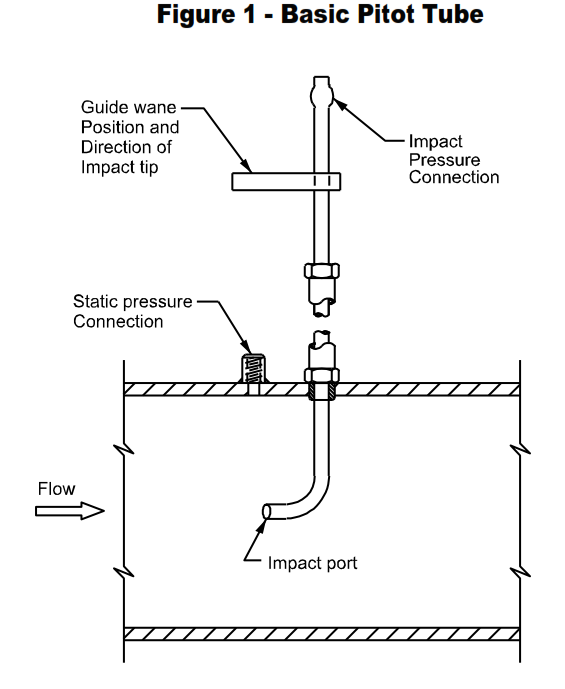
- A basic pitot tube is illustrated on Figure 1. The impact tube has a short section bent at an angle of 90 degrees to the main body of the tube. In use, the tube is positioned so the open end of the short section faces directly into the fluid stream. The inside diameter of the tube is approximately 1/16 to ¼ inch. The static pressure tap is in the wall of the pipe and is located upstream of the impact tube where the pressure reading will not be affected by the turbulence generated by the tube.
- These impact tubes are available in stainless steel for pipe sizes ranging from 3 to 24 inches and for pressures and temperatures up to 70 psig and 1600 °F (870 °C). On special order, longer elements can be provided.
-
Hemispherical and Conical Pitot-Static Tubes
- Hemispherical and conical pitot-static tubes are shown on Figure 2. These are considered basic elements and are designed and fabricated for maximum accuracy and repeatability. However, they are sensitive to damage such as dents and nicks at the impact and static pressure ports, and changes in the condition of the polished surface of the outer tubes. Values for the diameter, D, between 3/16 and 5/16 inch are considered acceptable.
- Tubes are available in stainless steel for pipe sizes ranging from 3 to 60 inches and for pressures and temperatures up to 70 psig and 200 °F (109 °C). On special order, tubes suitable for 1000 psig can be provided. The flow coefficient (K) for conical and hemispherical tubes is 1.00 when fabricated in accordance with American Society of Mechanical Engineers (ASME) or American Society of Heating, Refrigeration and Air Conditioning Engineers (ASHRAE) specifications.
.
-
Straight-Form Pitot Tube
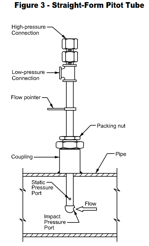
- A straight-form pitot tube is shown on Figure 3. Pitot tubes of this type generally are available for pipe sizes ranging from 3 to approximately 30 inches and for pressures and temperatures up to 100 psig and 750 °F (399 °C). Larger sizes and elements suitable for 1000 psig can be obtained on special order. Common materials of construction are brass and stainless steel. The flow coefficient ( K) generally is about 0.65.
-
Combined Reverse Pitot Tube
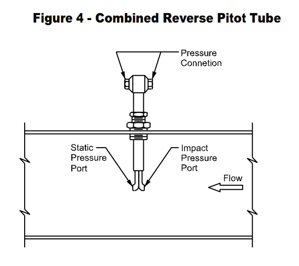
- A combined reversed pitot tube, also known as an S-type pitot is shown on Figure 4. In this type, the static pressure port is replaced by a reversed impact pressure tube. The pressure indication from the reversed tube will be lower than the true static pressure due to the suction developed by the fluid as it flows past the opening. As a result, a higher differential pressure is obtained for a given flow rate or fluid velocity.
- This type usually is available for pipe sizes as small as 3 inches and mast lengths up to 8 feet and for pressures and temperatures up to 70 psig and 1000 °F (538 °C). On special order, mast lengths up to 50 feet and water-cooled elements suitable for 2000 °F (1093 °C) (12 feet maximum length) can be provided. This type is available in stainless steel with a flow coefficient (K) of about 0.80.
-
Pitot-Venturi
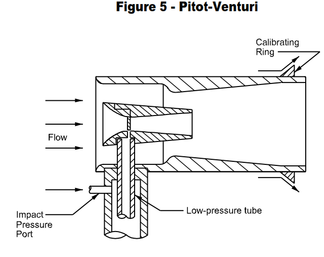
- The pitot-venturi tube is designed to provide a greater differential pressure for a given fluid velocity than that provided by a conventional pitot tube. The differential pressure magnification is obtained by lowering the static pressure. Depending upon the design of the element, the fluid, and the fluid velocity, differential pressures can range from about 5 to 10 times greater than those obtained with conventional pitot tubes. Pitot-venturi elements are available in brass and stainless steel for pipe sizes from 4 to 40 inches and for maximum pressures of 100, 300, and 1000 psig and maximum temperatures of 750 °F (399 °C) and 1500 °F (816 °C).
- The pitot-venturi tube is illustrated on Figure 5. The inner venturi terminates in the lowpressure throat of the outer venturi. As a result, additional fluid is drawn through the inner venturi, causing a further increase in the velocity with a correspondingly lower pressure at the inner throat. This is amplified further by the calibrating ring which produces an outward swirl of the fluid immediately downstream, resulting in a pressure decrease at the exit of the outer ventur
-
Averaging Pitot Tube
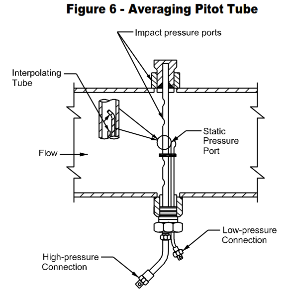
- The averaging pitot tube, Figure 6, senses impact pressures by means of a series of precisely located ports facing into the fluid stream. The impact pressures are averaged in the plenum and the average pressure at the center of the plenum is sensed and transmitted to the receiving instrument by the interpolating tube. The pressure indication from the downstream reversed tube will be less than the static pressure due to the suction created by the fluid flowing past the opening.
- The averaging pitot is available in several types depending upon pipe size and fluidvelocity. The type illustrated on Figure 6 is available for pipe sizes 4 to 24 inches and differential pressures from 500 inches of water in the smallest size to 40 inches of water in the largest size. The maximum pressure rating is 2500 psig from – 20 to200 °F (- 29 to 93 °C).Other types are available for pipe sizes ½ to 180 inches, differential pressures ranging from 400 to 4.5 inches of water, and pressure ratingsup to 2100 psig. Larger sizes are available on special order. Materials of constructioninclude stainless steel, steel, Monel, Hastelloy C, and titanium. The flow coefficient(K), calculated on the basis used for pitot tubes, is approximately 0.70.
-
Kiel Probe
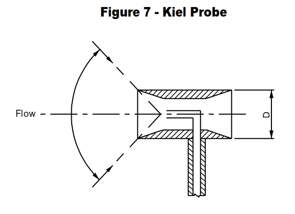
- The Kiel probe shown on Figure 7 is typical of several available designs of total pressure or impact tubes. These probes are employed to measure total pressure in fluid streams where the direction of flow may vary with operating conditions. A separate static pressure tap is required if the kinetic pressure is to be determined.
- The probes are accurate within one percent when the direction of flow is within a prescribed cone as shown on Figure 7. The angle of the cone varies from approximately 95 to 125 degrees depending upon the diameter (D) of the probe head. Head diameters range from 1/16 to ¾ inch. Kiel probes are available in stainless steel with mast lengths from 4 to 24 inches and for pressures and
temperatures up to 1000 psig and 2000 °F (1093 °C). Other materials and mast lengths are available on special order. -
Directional Probes
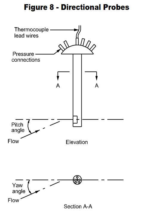
- Directional probes that measure static and total pressures and, in addition, determine direction of flow are available in several designs and sizes. These probes have either 3 or 5 ports. Those with 3 ports (2-dimensional probes) will indicate the yaw angle (Figure 8) and static and total pressures. Probes with 5 ports (3 dimensional) will indicate yaw angle, pitch angle up to about 40 degrees (Figure 8), and static and total pressures. No limitation is stated for the yaw angle because in operation the probe is rotated until the yaw angle is zero (the probe axis coincides with the direction of flow).
Either probe can be supplied with an integral thermocouple for measuring the temperature of the fluid. - Maximum velocity is limited to about 800 feet per second of gas. Minimum velocities are limited only by the capabilities of the secondary instruments. The probes are designed for determining gas velocity and flow direction in combustion chambers, ducts, flues, stacks, regenerators, and gas recirculation zones. They are available in stainless steel with mast lengths up to 24 inches and
pressures and temperatures up to 1000 psig and 2960 °F (1627 °C). Other materials and mast lengths are available on special order. -
Impact Tube Rotameter
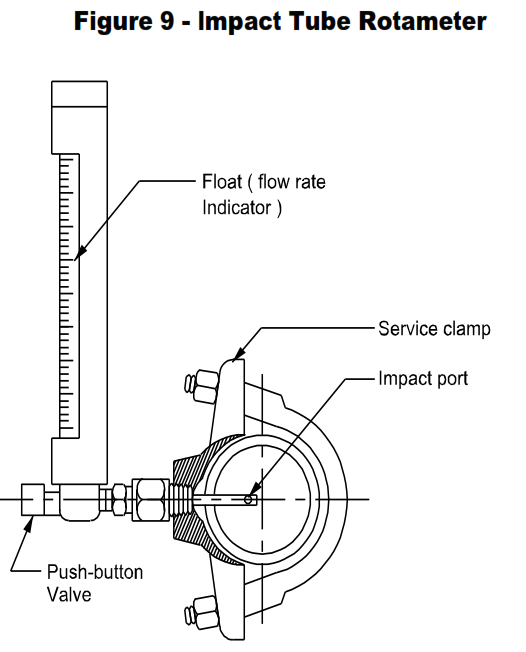
- An impact tube rotameter for water service is illustrated on Figure 9. Pressing the push-button valve permits water to enter the impact port, flow through the meter, and discharge through a static port into the pipeline. The scale reading at the float position indicates the total flow rate in the pipeline. Release of the valve button stops flow through the rotameter. The unit is available for pipe sizes from 1 to 16 inches and may be installed with a service clamp as shown, or in a bushing welded on the pipe.
- Calibrated for Schedule 40 pipe, the meter is accurate to within 5 percent of maximum flow rate for pipe sizes 1-1/2 through 16 inches and within 10 percent for the 1 and 1-1/4 inch sizes. Ranges are 8 to 1 or 10 to 1 depending upon the maximum flow rate of the unit. For maximum accuracy, 10 straight pipe diameters upstream (20 diameters for 1, 1-1/4, and 1-1/2 inch sizes) and 5 straight diameters
downstream are required. Wetted parts are brass and glass. Maximum operating pressure and temperature are 175 psig and 240 °F (116 °C). -
Piccolo Tube
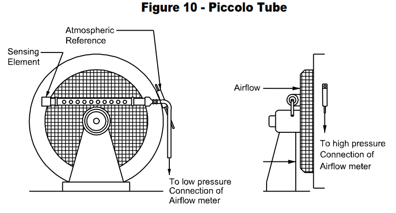
- An effective, inexpensive means of measuring airflow, is a piccolo tube that can be used to obtain about 1-inch water column differential pressure at maximum flow rate. The pipe is attached to the Fan Inlet Screen. Any position on the screen is acceptable. The holes must be on the screen side shown on Figure 10 facing the fan. The fan discharge cannot be directly obstructed by a damper unless an inlet cowling is provided. Such an obstruction can cause suction turbulence which can affect flow measurement. Fans with two dampered inlets require piccolo tubes on each inlet with
outputs connected together to meter low pressure connection. - The sensing element consists of a one-inch standard weight pipe, with 1/8-inch or 3/16-inch diameter holes on 3-inch centers, drilled through one wall only. A pipe cap is screwed on one end and a reducing coupling to 3/8-inch tube on the other. The sensing element is mounted on inlet screen with holes facing the fan.
- The atmospheric reference is a ½-inch tube 8 inches long with one end crimped two inches to provide for a 5/16-inch mounting hole. The atmospheric reference is installed on the fan housing away from drafts. A 3/8-inch tube is inserted as shown on Figure 10 for the high pressure connection.
Pitot Tube Design Requirement in Process Industry
- Applications for pitot-type primary elements are restricted somewhat by fluid characteristics and operating conditions. However, these elements are of value under certain conditions where other measurement devices are impractical or inoperable due to low-operating pressure, low-fluid velocity, excessive pipe size, and limited room. Also, they are useful where permanent pressure loss must be low, high accuracy generally is not required, and installation and maintenance costs must be minimized. Frequently, the installation can be designed to permit insertion and removal without shutdown.
- Pitot type elements offer minimum restriction to the flowing fluid; consequently the permanent pressure loss is considerably lower than that for differential pressureproducing elements. For pitot-static tubes, the Kiel probe, and the pitot-venturi tube, the permanent pressure loss generally is insignificant. The permanent pressure loss obtained with the averaging pitot is somewhat greater. As percent of differential pressure, the permanent pressure loss varies progressively from less than ¼ to about 7 per-cent for pipe sizes from 40 to 2 inches, and 8 to 20 percent for pipe sizes 1-1/2 to ½ inches.
- Because of the low permanent pressure loss, pitot-type elements can be used where the static pressure or the fluid velocity is too low to produce sufficient differential pressure with flow-restricting elements. Also, they can be used for high-velocity applications without developing excessive permanent pressure loss.
- When fluid velocities are high, the elements shall be braced or supported to prevent them from being deflected or broken by the force or drag of the flowing fluid. With the exception of the Kiel and directional probe, deflection or pitch angle should not exceed 2 degrees (deflection divided by the element length should be less than 0.03). Deflection correction factor data can be provided by some manufacturers.
- With the exception of the Kiel and directional probes, the yaw angle should not be greater than 7 degrees for pitot static and averaging pitot tubes and not more than 5 degrees for the pitot-venturi tube if maximum accuracy is required.
- Standard pitot-static tubes with hemispherical, modified hemispherical, or ellisoidal tips are less sensitive to pitch and yaw. Errors in impact and static pressure measurements increase quite rapidly above 5 degrees but tend to compensate each other so that the resulting error increases to only about 2 percent with pitch or yaw angles of approximately 30 degrees. Because of the configuration of these elements, pitch and yaw errors are identical.
- In general, fluids should be clean and gases should contain a minimum of entrained liquid in order to avoid excessive errors.
- Serious measurement errors can develop if droplets of liquid collect in pitot elements and connecting lines on gas service. If the reading on the secondary instrument does not drop smoothly to zero when flow ceases, the presence of liquid droplets is indicated. The system should be blown out thoroughly with dry air or inert gas. It may be necessary to heat the pitot tube to dry it completely.
- Where dirty fluids must be metered, the elements shall be purged. However, because of the relatively low differential pressures developed in pitot-tube elements, they are extremely sensitive to the flow rate of the purging medium. Not only must the purge rate remain constant but the measured differential pressure shall be corrected for the decreased reading resulting from the purge flow. Some manufacturers can provide correction factor curves.
- If purging is not feasible, a periodic blowback system can be considered where purge fluid can be introduced periodically to blow foreign material back into the process line. Blowback systems have been used effectively on stack installations to remove fly ash from the pitot elements.
- Where the pitot-venturi tube is used for differential pressure magnification and the fluid contains particles likely to plug the impact port, the manufacturer may relocate the impact port (about 135 degrees) to the downstream side of the support mast. When this is done, some inconsistency in readings will be observed due to the turbulence induced in the fluid by the mast.
- Pitot-type elements generally are not suitable for liquids having viscosities above 50,000 SUS (10,500 centistokes), such as waxes and tars, because of the tendency of the fluids to form static layers at the sensing ports.
- Pitot-type elements are fabricated with tubes of various diameters, usually ranging from 1/16 to ¼ inch. The time constant generally is very short for tubes down to 1/8 inch diameter but increases rapidly for smaller diameters. For this reason, 1/16 inch OD is the smallest recommended size for ordinary use.
- Using simple manometer hookups, the time constant will range from about 15 to 60 seconds with 1/16-inch pitot tubes. If the size is reduced to 1/32 inch, the time constant can be as high as 15 minutes.
- Too short a time constant may require the use of a choke to slow down the response time and dampen random fluctuations which make taking average readings very
difficult. The desirable time constant range is about 2 to 20 seconds. - Impact port diameters ¼ inch and larger can be considered for pipe sizes greater than 20 inches. However, dirt accumulation in the element becomes an increasingly serious problem as the port size is increased.
- Fluid velocities encountered in industrial applications usually are not high enough to exceed the capabilities of pitot-type elements (provided the mast is capable of withstanding the force of the fluid without exceeding deflection limitations).
- Depending upon the type and design of pitot element, maximum permissible velocities on air and gas service usually are limited to values between about 700 and 1150 feet per second due to the formation of shock waves in the vicinity of the element. Maximum liquid velocities generally are somewhat higher.
- Because of the abrasive action of superheated steam and the critical nature of the clearances in pitot-venturi type elements, these elements shall not be used for these applications. Manufacturers’ recommendations should be obtained for other types of elements where the velocity of the superheated steam exceeds 150 feet per second.
- Element type, design, size, manufacturing tolerances, size of impact port, fluid characteristics, and capabilities of secondary instruments are some of the selection influencing factors which should be considered when fluid velocities are low.
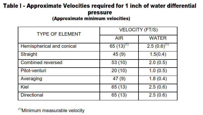
- Table I lists approximate velocities for air and water which will produce a differential pressure of one inch of water. This differential pressure was selected on the basis that one inch of water is the minimum that can be measured with a reading error of one percent using an inclined manometer.
- Table I also lists (in parentheses) the approximate minimum measurable velocities without consideration being given to the method of measuring the differential pressure. For example, the minimum measurable velocity for the hemispherical pitotstatic tube is about 13 feet per second. Since differential pressure varies directly as the square of the velocity, 13 feet per second will develop a differential pressure of (13/70)2 or about 0.035 inch of water. A micromanometer will measure differential pressures of this magnitude accurately but the tedious procedure is unsuitable for industrial applications.
- At very low-fluid velocities, the total pressure begins to affect the accuracy of the indicated velocity pressure. When velocities approach the minimum values listed in Table I, the manufacturer of the element should be consulted.
- Certain basic requirements should be observed when installing pitot-type elements.
- Except for directional probes, straight runs of pipe upstream and downstream of the elements are required. Lengths of runs depend upon the element type and the configuration of the upstream piping and will vary from about 7 to 25 pipe diameters upstream and from about 1-1/2 to 4 pipe diameters downstream. The use of American Gas Association (AGA) or American Society of Mechanical Engineers (ASME) straightening vanes will reduce unstream straight run requirements to about 6 to 9 pipe diameters. Often a strong swirl component exists in straight pipe and can result in large errors unless straightening vanes are installed.
- Connecting lines between the elements and the secondary instrument should slope at least one inch per foot to eliminate entrapped air or liquid.
- Seal and condensate chambers should be at equal elevations, filled to equal levels, and should not be supported from the elements.
- On steam applications the lines to seal chambers shall be insulated to prevent localized condensation and erratic readings. If the steam has high superheat, insulation may not be required.
- For gas applications, the element connections shall be on the top or side of the pipe to keep moisture and dirt from entering the connecting lines. For liquid service, the connections should be on the side of the pipe below the centerline or at the bottom to keep the lines filled with liquid.
- Systems shall be leak checked. This may be done by using a manometer and pressurizing the system. The manometer reading should remain steady for at least one minute.
- If the system has a long time constant, the manometer reading should remain steady for a period of at least twice that of the time constant.
- Flow-measurement accuracy obtained with pitot type elements depends upon a number of factors. These include manufacturing tolerances, sensitivity to localized flow patterns, physical condition of the element and fluid, stability of the velocity profile of the fluid, and the accuracy of the relationship between measured and average velocities.
- Flow coefficients can vary as much as plus or minus 5 percent due to manufacturing tolerances. Accordingly, specifications should state the element must be flow calibrated. Since the flow coefficient will vary with Reynolds number for some elements, a velocity versus differential pressure calibration curve is preferred to a flow coefficient.
- Elements sometimes are provided with a flow rate versus differential pressure calibration curve. The curve is based upon positioning the element either at the point of maximum velocity or where the velocity is considered to be equal to the average velocity. In either case, the calibration curve is based upon an idealized velocity profile in the pipe, a condition not likely to occur in an actual installation.
- Accuracy statements by manufacturers usually range from 0.5 to 1.0 percent error.The stated error refers to the relationship between velocity and differential pressure, not between velocity and flow rate (the averaging element is an exception). The user shall determine the average velocity as well as the relationship between the average velocity and the velocity at the point where the element will be positioned during normal operation. Depending upon the accuracy with which this relationship is established, a properly installed system can be expected to have an overall system error between 2 and 5 percent.
- For maximum accuracy, pitot elements, including averaging types, should be field calibrated. Usually this is not feasible and, except for averaging elements, the average fluid velocity shall be determined by making a traverse, that is, taking a number of differential pressure readings with the element positioned at prescribed locations in the pipe.
- There are four common methods for determining traverse points and average velocity: Centroid of Equal Areas, Newton-Cotes, Chebyshef, and Gaussian. These methods are discussed in the ASME publication, Fluid Meters, Sixth Edition. Standard H3T is based upon the Centroid of Equal Areas method and provides procedures for determining traverse points in round and rectangular pipes and ducts. The standard also includes a sample calculation.
- When making the traverse, the flow rate should remain constant or serious errors may result. The flow rate may be monitored by installing a second pitot element. This element should be located where it will not influence traverse readings and where the velocity is relatively high. If a constant flow rate cannot be maintained, each traverse reading should be adjusted an amount proportional to the deviation of the monitored reading from a selected base value. A traverse reading should not be considered valid if the monitored reading has changed more than 5 percent since a significant
change in the velocity profile may have occurred. - After the velocity profile, average velocity, and flow rate have been determined, a reference position for the measuring element should be selected. Generally the element is positioned at the average or maxi-mum velocity, but any point may be selected provided the correct factor is used to convert the indicated velocity to average velocity.
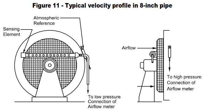
- Figure 11 illustrates a typical velocity profile in an 8-inch pipe. Inspection indicates the pitot element may be located either at the average velocity, point A, or at the maximum velocity, point B. At either position the velocity change is gradual, minimizing the need for precise positioning of the element. The element should not be located at point C since a small error in position will result in an
appreciable measurement error.
- As an example, assume point B is selected as the element reference position and the average velocity is 66.5 percent of the velocity at B. A differential pressure reading obtained during operation is converted to the equivalent velocity by referring to the calibration curve supplied by the manufacturer . The velocity is multiplied by 0.665 to determine the average velocity and this is multiplied by the cross-sectional area of the pipe to obtain the flow rate. If a calibration curve is not available but the flow coefficient of the element is known, velocities can be calculated using the
formula
where
v = Fluid velocity, ft/sec
K = Flow coefficient, dimensionless
h = Kinetic pressure, inches of water (dry)
Ρ = Fluid density at flowing conditions, lbs/ft3
- It is possible the velocity profile at a given flow rate may be appreciably different at lower or higher flow rates and the simple procedure in 3.11 will not be sufficiently accurate. Since specific guidelines cannot be provided, the user must develop a suitable procedure. It may be necessary to develop velocity profiles for several flow rates in order to construct a correction factor curve to be applied to indicated differential pressures when converting to average velocities.
- For flow rate correction formulas applicable to pitot-type elements.
Pitot Tube Advantages
- Installed costs for pitot-type elements usually are lower than those for other differential pressure-producing elements. For pipe sizes 2 inches and less, costs
probably will be equal for pitot element and orifice plate installations. As the pipe size increases above 2 inches, costs for pitot element installations will be relatively lower, decreasing to about 50 to 60 percent of an orifice plate installation in 8-inch pipe. - Pitot tubes provide convenient, low-cost methods of comparative flow measurement.
- The element size usually is small in relation to the pipe diameter so that no appreciable permanent pressure loss occurs.
- Most elements can be inserted through a comparatively small hole in the pipe.
- In many cases, installations can be designed to permit insertion and removal of elements without shutdown.
- Portability of elements permits measurement of local velocities.
- Most elements can be applied to measurement of flow rate in a wide range of pipe sizes.
- Pitot elements are available in a variety of types for applications unsuitable for other methods of flow measurement.
- Elements amplifying differential pressures as much as 10 times are available.
Pitot Tube Disadvantages
- Obtaining and maintaining high measurement accuracy can be difficult, particularly if flowing conditions vary.
- Since the velocity profile of the fluid may vary with the flow rate, a traverse for each operating condition may be required.
- Differential pressures are low and usually noisier than those produced by orifices, flow nozzles, and venturi tubes.
- Except for the averaging pitot tube, only one filament of the fluid stream is measured by the element, making it necessary to traverse the stream to relate readings to flow rate.
- Maintaining initial accuracy is highly dependent upon preserving the physical condition of the element ports. Distortion, burrs, nicks, dents, and dirt can affect readings seriously.
- Since the flow rate is proportional to the square root of the differential pressure, the measuring range is limited to about 3 to 1.
- Straight runs of pipe upstream and downstream of the element are required.
- Straightening vanes may be required.
- Except for amplifying elements (pitot-venturis), for a given flow rate the differential pressure is about one-fourth that developed by an orifice plate with maximum beta ratio.
- Because of the quadratic character of calibration curves, damping devices do not provide true average values.
Pitot Tube Precautions
- Installations shall be leak tested, particularly on gas applications where differential pressures are low.
- Some pitot venturi designs are affected by turbulence and, in some cases; gain varies with fluid velocity. For maximum accuracy, these elements should be calibrated against a standard pitot-static tube or other flow standard under similar conditions.
- Where static pressure is measured with a pitot-static tube, the cross-sectional area of the probe should not exceed 1 percent of the total passage area in order to avoid
measurement errors due to increased fluid velocity along the probe. - If the use of a standard element with a diameter less than 3/16 inch is indicated, an impact tube and separate static connection are recommended.
- If static pressure is measured with a wall tap, the tap should be located in a smooth section of the wall and at least 10 probe diameters upstream from the probe stem.
- With the exception of standard hemispherical and conical pitot-static tubes and directional probes, pitot-type elements do not measure true static pressure. To determine velocity or flow rate from indicated differential pressure, the flow coefficient or a calibration curve must be obtained from the manufacturer.
- If the element is provided with a flow rate calibration curve, the element must be positioned according to the manufacturer’s specifications. Calibration curves may be based upon positioning the element either at the center of the pipe or at the theoretical average velocity.
- A manufacturer-calibrated element must be installed in the specified pipe schedule to avoid gross errors
- Elements may require bracing due to deflection caused by fluid drag.
- Where gases contain condensibles or liquids contain dissolved gases or bubbles, special installation precautions must be observed.
- If impulse lines are purged, the effect on the differential pressure must be determined. The purge rate must be constant to avoid serious errors.
- Condensate or seal pots may be required.
- Elements should be removed periodically and cleaned internally and externally.
- Pitot-venturi elements should not be used in pipelines smaller than 4 inches because the reduction in the free area of the pipe produces a differential pressure which is not indicative of the true fluid velocity.
- Pitot-venturi elements are sensitive to dimensional changes. The elements must be kept free of deposits and maintenance operations shall not change the throat diameter or surface finish.
- The gain or amplification developed by pitot-venturi elements varies with Reynolds number. A velocity versus differential pressure calibration curve should be obtained from the manufacturer.
- If a pitot-venturi element is provided with a calibrating ring, the position of the ring shall not be changed. For each 1/32-inch shift, an error of about 1 percent may be introduced. The element is scribed to show the correct position of the ring.
- Elements may vibrate at high fluid velocities, resulting in elastic fatigue.
- When an accurate traverse is made with a standard pitot-static tube, readings should not be taken closer than 5, preferably 10, tube diameters from the wall of the pipe. At 10 diameters, static pressure readings begin to be affected by the venturi effect developed between the element and the wall.

