1.0 PURPOSE.
2.0 SCOPE.
3.0 APPLICABLE DOCUMENTS.
4.0 RESPONSIBILITY.
5.0 MANPOWER.
6.0 TOOLS & EQUIPMENT.
7.0 METHODS/PROCEDURE.
8.0 QUALITY CONTROL.
9.0 SAFETY PRECAUTION.
10. ATTACHMENTS.
PNEUMATIC TESTING PROCEDURE FOR MECHANICAL EQUIPMENT (CONVECTION, CROSS-OVER & RADIANT COIL)
1.0 PURPOSE
This method statement shall provide minimum guidelines to carry out pneumatic testing works in plants and refinery projects.
2.0 SCOPE
This Method Statement covers the procedure of pneumatic testing of mechanical equipments, pipelines (Convection, Cross-over & Radiant Coil) for plants and refinery projects.
3.0 APPLICABLE DOCUMENTS
3.1 Project Specifications and Standards
3.1.1 ASME 31.3 Process Piping.
3.1.2 ASME Section V, Article 10 and Article 10 Appendix I (Reference SAES-A-004 Para 5.6.3).
3.1.3 S-000-3160-004 Piping Pressure Test Procedure.
3.1.4 S-000-3160-007 Piping Internal Cleaning Procedure.
3.1.5 SAEP-302 Instruction for Obtaining a Waiver of a Mandatory Saudi ARAMCO Engineering Requirements.
3.1.6 SAES-A-004 General Requirements for Pressure Testing.
3.1.7 SAES-A-104 Wastewater Treatment, Reuse and Disposal.
3.1.8 SAES-L-150 Pressure Test of Plant Piping and Pipelines.
3.1.9 SATIP-A-004-01 Pneumatic Pressure Testing.
3.1.10 SAIC-A-2001 Review Procedure – Pressure Testing (All Applications).
3.1.11 Construction Safety Manual.
3.1.12 Schedule “Q” Quality Requirement.
4.0 RESPONSIBILITY
4.1 Construction Manager is responsible for implementing HSE and shall study, analyze and schedule all construction activities with his department to include manpower and equipment line up as well as other possible resources required for the successful implementation of the construction work activities. Study all aspects of work procedure as per JV Technical Scope of Work.
4.2 Hydrotest Supervisor shall assist Construction Manager in the overall construction activities. Receives and carries out directives and strategies of Construction Manager in various phases of duties assigned by this immediate Supervisor.
4.3 Hydrotest Foreman shall be responsible for the direct work supervision at site and ensure that the work is performed in accordance with JV Technical Scope of Work and specification.
4.4 QC Engineer/Inspector shall be responsible to verify the work and ensure that the work is being performed in accordance with the water disposal procedure.
4.5 QC Group shall prepare all required documents for water disposal and will lead in coordinating with proponent and client to witness and accept the work.
4.6 Safety Supervisor/Officer shall monitor and ensure that the work is done in accordance with JV Safety Standard Procedure and in accordance with Saudi ARAMCO Safety Standard Procedure.
5.0 MANPOWER
5.1 The Hydrotest Supervisor shall control the overall activity of testing works and he shall be directly reporting to the Construction Manager. The basic manpower under him shall consist but not limited to the following:
5.1.1 Piping Foreman.
5.1.2 Pipefitters.
5.1.3 Welder.
5.1 .4 Rigger.
5.1.5 Crane Operator.
5.1.6 Helper.
5.1.7 Scaffolder (by others).
5.2 QC Inspector.
5.3 Safety Supervisor/Officer.
6.0 TOOLS AND EQUIPMENT
6.1 Tools and equipment needed should be in good condition and must be checked by Hydrotest Supervisor & Safety Officer prior to use. These includes but not limited to:
- Sets of wrenches
- Hand Tools
- Air compressor
- High Pressure hose
- Test Manifold
- Pressure Gauge
- Pressure Relief Valve
- Temporary Spool
- Test Blind
- Test Blind
- Temporary support
- Temporary material
- Crane
- Welding machine
6.2 Test Manifold
6.2.1 Before employing the pressure testing manifold in the actual system pressure test, it shall be separately pressure tested to at least 1.2 times the system test pressure but not less than the discharge pressure of the pump used for the pressure testing.
6.2.2 The test manifold shall be designed and constructed to meet the minimum system requirements and approved by the Engineering Division Head in operating facilities or responsible Project Inspection Division Head in new construction
6.2.3 Test manifold shall have 100% NOT of all welds.
6.2.4 Test manifolds for new construction shall be revalidated for each new project and every 60 months for operating facilities.
7.0 METHODS/ PROCEDURE:
7.1 Preparatory Works
7.1.1 Secure work permit from DEC/JGC concerned personnel prior to start of work/activity
7.1.2 Prepare all materials needed for the job.
7.2 General Requirements
7.2.1 General Instruction Gl-0002.102 “Pressure Testing Safely” shall be followed during pressure Testing
7.2.2 Pneumatic Testing
7.2.2.1 Pneumatic testing is not permitted without written approval of the manager, Inspection Department, unless specifically allowed by this standard or the referenced Saudi Aramco SAESs or SAMSSs. This test, when conducted, shall be in accordance with Gl-0002.102 for additional safety requirements.
7.2.2.2 Pneumatic testing with air of piping systems or equipment which has been in flammable service shall be concurred by the Manager, Loss Prevention Department.
7.2.3 Test Package preparation and handling shall be in accordance with approved procedure.
7.2.4 Approved Test Package shall be made available for reference in setting up the pressure test of line or system.
7.2.5 Prior to test, weld lines shall be thoroughly dry, cleaned of rust, grease, paint, or other contaminants.
7.2.6 It shall be confirmed that NDE records (MT, PT, RT, UT) showing extend, sequence on NDE selection meeting project specification, line check, line internal cleanliness check as required have been completed and approved and all “A” punch items are completed prior to the release of line for pressure testing.
7.2.7 Flange joints shall be checked for tightness or other possible sign of leaks. All flanges shall be securely taped and pinhole provided in the tape for leak detection.
7.2.8 Pipes shall be sufficiently supported. All anchors, supports, guides and hangers shall be checked for correct installation. Expansion joints with tie rods and retaining nuts shall be installed in the test position in accordance with manufacture recommendation and spring hangers or springs supports shall be provided with temporary restraints where needed to prevent excessive travel or deformation under test loads.
7.2.9 Test shall not be done with the instrument connected. Test shall be carried out for the piping up to the first valve of instrument pressure piping. In this case, if flange or union is installed at instrument side of the first valve, such flange or union shall be kept disconnected during the test. Test lines shall be sealed to prevent dust or egress induced to the instrument pressure piping.
7.2.10 All valves in the test system shall be fully open.
7.3 Test Preparation
7.3.1 Preparation of pressure test shall be in accordance with SAES-A-004
7.3.2 Temporary blind flanges and test blinds shall be installed at locations shown on the mark P&ID and isometric drawing included in the test package. Test blind shall be in adequate thickness to withstand the test pressure; test blind should be lifted and installed by using flange jack which is the special jig for safety and easy installation.
7.3.3 Temporary gasket shall be installed at test limit and shall be equivalent to permanent gasket for 600# and higher rating and all RTJ lines.
7.3.4 Equipment such as drums, heat exchangers, pumps, tanks, etc. that is not to be tested shall be either disconnected from the piping or isolated by blinds or means during pneumatic testing.
7.3.5 For piping system with check valves, the pressure shall be from the upstream of the check valves or the internal of the check valves can be removed under Company supervision. Check valve shall not be used for isolation.
7.3.6 Stopper of spring supports shall not be removed before pneumatic test.
7.3.7 Instrument connections shall be closed with proper gasket and blind flange and tubing from instrument root valve is to be disconnected.
7.3.8 Blind Flanges, paddle blinds or spectacle blinds shall be used to isolate the test sections. They shall be the same class rating of the system or may be fabricated from verifiable identification of base material and approval of calculations by the supervisor, CSD Piping Unit when this is not practical closed block valves (gate, globe, plug and ball may be used to isolate the piping sections (providing the valves are not passing, otherwise the spectacle plate/blind shall be installed in the closed position. If block valve are used in lieu of blinds, provisions shall be made to ensure no overpressure can occur in the system that is not being tested, due to possible leak through the valves.
7.3.9 The following components shall removed or isolate by inserting blinds and or temporary spools:
7.3.9.1 Control valves, thermo wells, orifice plates, restriction orifice, strainer elements, filter elements, rupture discs, flow nozzles, displacement and turbine meters, self contained regulators, rota meters, pressure gauges, level gauges, level instruments, Conical Strainers, flow glasses, sample probes, safety showers and eye washers, non-slam check valves, dual plate check valves, pressure relief valves, steam traps, auto drains, sample coolers and chemical injections.
7.3.10 The piping systems shall be cleaned in accordance with SAIC-L-2017 and SATR-A-2008.
7.3.11 Pressure gauges shall be calibrated prior to its use. Calibration interval shall not exceed one (1) month as mentioned in Section 8 Para.8.1.5 of SAES-A-004 “General Requirements for Pressure Testing. Calibration certificates shall be included in the Test Package.
7.3.12Calibrated pressure gauges shall be installed at appropriate locations. All gauges shall have a range such that the test pressure is within 30-80% of the full range. A minimum of two pressure gauges shall be installed on the system, one on the pressure control point and the other on the test system.
The accuracy of the gauges shall be within 5% tolerable accuracy. Sketch showing location of the gauges vis-~-vis highest and lowest point are included in the test.
7.3.13Pressure relief valve shall be calibrated within one week prior to test date and shall have adequate capacity set to relief at 5% above the test pressure. It can be set 10% above the test pressure if the test pressure is less than 85% SMYS. Refer to ASME B31.3-2008 Table A-1 for values. Calibration report shall be inserted into the Test Package.
7.3.14The following shall be excluded from the pneumatic test. Refer to SAES-A-004 Para. 8.2. Also, other unlisted sensitive equipment or as designated by Saudi Aramco Piping Standards Committee or other equipment specific Saudi Aramco Standards Committees can be added.
- Rotating machinery, such as pumps, turbines and compressors.
- Strainers and filter elements.
- Pressure relieving devices, such as rupture disks and pressure relief valves.
- Locally mounted indicated pressure gauges, where the test pressure will exceed their scale range.
- Equipment that cannot be drained.
- Instrument devices.
- The piping system shall be accessible for visual inspection during leak testing and to ensure that all weld joints, threaded joints, flange joints shall be left exposed no cover up of masking tape, unprimed and unpainted for examination during leak testing.
7.4 Pneumatic Test
7.4.1 Identify the test limit shown on the Test Package. (Test package to be reviewed separately)
7.4.2 Prepare test equipment and test manifolds to the designated location.
Pressure gauge shall be installed at the highest point of the line injection of pressure through a test manifold. Test manifold shall be at the lowest point of the line.
7.4.3 Review each test package and assure pre-test checklist has been completed and accepted by QC and permitted to test.
7.4.4 Close all the open ends of the piping system to be tested, valves to install plug, cap, or blind flange, and equipment terminals. Provide temporary spool piece for those excluded pieces, etc.
7.4.5 The area around the system to be tested shall be cleared of unauthorized personnel and warning notices shall be posted during the time that piping system is pressurized for the test. No one shall approach the test area for a minimum of 10 minutes after the test pressure is reached and before commencement of inspection of the system, the isolation valve between the temporary test manifold/piping and the piping/equipment under pressure test shall be closed and the test pump disconnected. The isolation valve
downstream of the manifold shall be opened after the pump is disconnected.
7.4.6 Two (2) personnel shall be at the pressure control point monitoring the gauge whenever the system contains pressure.
7.4.7 Take a temperature reading of metal to assure that it is warmer than the coldest temperature allowed.
7.4.8 Test medium will be introduced to the system using air compressor. The test medium “dry air” shall be introduced into the piping system gradually until the pressure is lesser than half of the test pressure. At this ‘point, the pressure shall be maintained for 10 minutes.
7.4.9 First leak detection shall be made for all welding and flange joints.
7.4.1 0The pressure rise during a pressure test shall be gradual and under control to allow time for material to strain, and time for personnel to check for leaks.
7.4.11 The pressure shall be gradually increased to the test pressure.
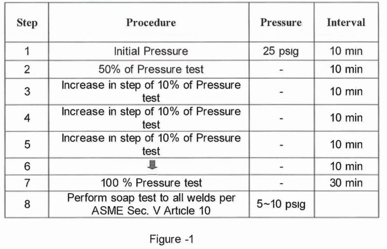
7.4.12For table shown on Figure-1 weaknesses are repaired and leaks are stopped before proceeding to any higher pressure.
7.4.13After attaining test pressure and before commencing line inspection of the system, the isolation valve between test manifold and piping under pressure test shall be closed and the compressor’s hose disconnected.
7.4.14Conduct visual inspection of the line to detect evidence of leakage.
7.4.15ARCC and DEC/JGC authorized personnel shall check the line for leaks.
7.4.16Cover joints and welds with Chloride-free leak detection fluid using a chemist’s wash bottle or other suitable means. Ordinary household soaps or detergents are not permitted. Also, the bubble forming solution shall be compatible with the temperature of the test conditions. Refer to ASME V Art. 10 Appendix I “Bubble Test- Direct Pressure Technique”.
7.4.17If leaks are found, marked the location of leaks and depressurized the line to pressure gauge dial indicating zero before any repair works or tightening of
bolts. After the repair, re-test the line as per above sequence.
7.4.18Maintain test pressure for sufficient length of time but no less than 30 minutes to permit thorough visual inspection of all joints and weld. Test pressure will be maintained not greater than two (2) hours after notification of client’s inspector. Pressure shall be reduced gradually when depressurizing. The depressurizing valve and piping shall be arranged for safe discharge of the test media upon completion of the test. Do not depressurize a system by loosening bolts in a flange or by unscrewing fittings. Authorized personnel shall open the vent’s valve gradually to prevent vacuum forming.
7.4.19Approved test forms shall be completed and signed by appropriate inspection personnel of Saudi Aramco.
7.5 Restoration
7.5.1 After completion of pressure test, permanent gasket and temporary gasket installed where to be reinstated shall be replaced to a new permanent gasket except for PIKOTEK gasket, ring joint gasket and rubber sheet gasket as mentioned in S-000-3160-004 Para. 6.8.
7.5.2 Remove all temporary materials used for the test. Reinstall all items temporarily removed during testing.
7.5.3 Inspect restoration of piping system, verify reassembly and flow arrow direction of valves and other miscellaneous components where applicable.
7.5.4 All plugged shall be installed and seal welded.
7.5.5 Endorse to DEC/JGC for inspection of reinstatement / restoration. If approved, sign Test Package Flow Sheet (Front Sheet) and Reinstatement / Final Checklist Test Package. Punched items by DEC/JGC shall be filled-up using Construction Punch list Form SATR-A-2007 and return for clearing.
7.5.6 Upon acceptance. Punched items shall be filled-up and returns to ARCC for clearing. If approved, Contractor shall sign checking Item on Test Package Flow Sheet (Front Sheet) and Reinstatement I Final Checklist of Test Package.
8.0 QUALITY CONTROL
8.1 QC Inspector shall be responsible to conduct all required inspection/documentation and to assure that all applicable requirements, codes and standards are complied with.
8.2 QC to monitor testing activities and sign documents as per SATIP-A-004-01
9.0 SAFETY PRECAUTION
Safety Requirement, arrangement of equipment and system to carryout safe pressure testing shall be in full compliance to the Saudi Aramco G.I 0002-102 “Pressure Testing Safely”
9.1 Construction Manager/Supt./Supv./FM shall be responsible for the implementation of this procedure and the required orientation necessary for the work force.
9.2 Safety Supervisor/Officer shall monitor compliance of the entire working crew regarding safety procedures until the work is fully completed.
9.3 In plant areas and shops the test area shall be barricaded and warning signs shall be posted to alert approaching personnel, where practical.
9.4 Personnel shall be posted at plant sites to keep the test area clear of all people not connected with the test, if necessary.
9.6 No work shall be carried out on system while system is under pressure.
9. 7 A test system under pressure shall never be left un-attended until test is de pressurized.
9.8 When testing at high elevation, strong and safe scaffold shall be prepared. Also ladder or mobile access lift can be used. No going out from the man basket into an elevated working platform.
9.9 The pressure rise during a pressure test shall be gradual and under control to allow time for material to strain, and time for personnel to check for leaks. Do not exceed the following pressures until weaknesses have been repaired and leak has been stooped.
9.10 Working on a system while it is under pressure is very hazardous because a failure could be initiated at the work due to the addition of stresses in material. Therefore, a system shall be depressurized (with the exception of pressure due to a head of liquid) before any work is done to stop leaks or repair weaknesses, including the tightening of bolts.
9.11 Upon completion of the test system should be emptied in such a way as not to cause vacuum and collapse. The depressurizing valve and piping shall be arranged for
safe discharge of the test medium upon completion of the test. Do not depressurize a system by loosening bolts in a flange or unscrewing fittings because this could lead to injury. Temporary gaskets shall not exceed the specified rating indicated by manufacturer’s data sheet or spiral wound permanent gaskets must be used for those ratings where temporary gaskets are not available.
9.12 Good housekeeping must be maintained for the duration of work.
9.13 Job Hazard and Risk Assessment (JHRA) of this method statement shall be disseminated and explained to workers for safety awareness.
10. ATTACHMENT:
Job Hazard and Risk Assessment
Test Package