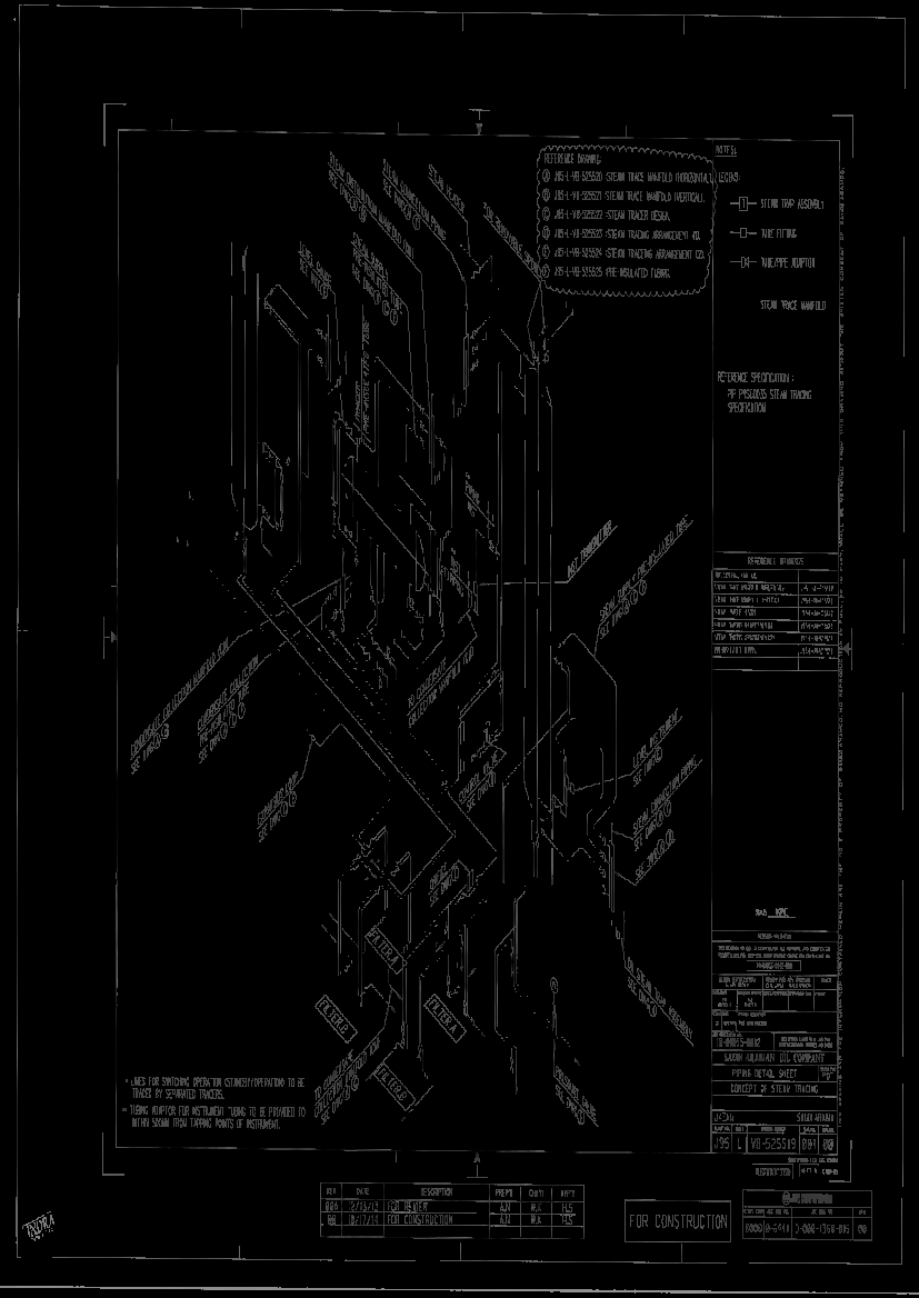
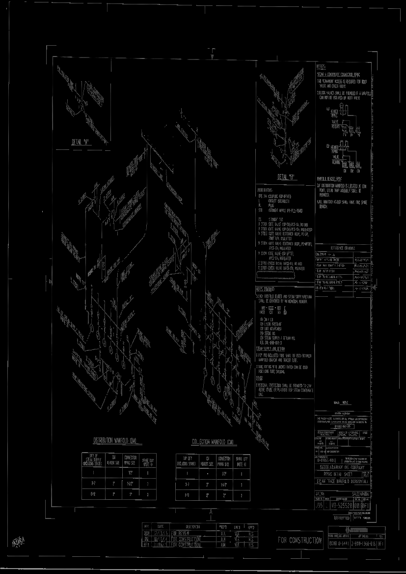
PROCEDURE FOR STEAM TRACING INSTALLATION AND TESTING
Tools and equipment needed should be in good condition and must be checked by Supervisor / Safety Officer prior to use in the construction area. These includes but not limited to:
1 Tube Bender
2 Tube Cutter and Dies
3 Welding Machine
4 Pipe Bender
5 Pipe Cutter and Dies
6 Electric Drill
7 Electric Grinder
8 Pipe Wrench
9 Combination Wrench
10 Grinding Machine / disc
11 Flat and Half Round File
12 Man-lift
13 Paint Marker
STEAM TRACING INSTALLATION
- The steam supply should staii at the highest point of the lines to be traced, and tracers an-anged so that flow is generally downward avoiding pockets as much as possible .
- Each tracer shall be continuous from the supply manifold to the trap with no vents, drains, or dead-end extensions at intermediate points. Branch connections shall be avoided.
- All Tracers shall be installed parallel to and against the heated pipe or equipment and shall be placed on the most accessible surface location in regard to supports, ease of installation, connection and thermal insulation. Multiple tracers shall be equally spaced around the circumference of the pipe.
- Tracer loops around flanges are horizontal so as to drain on shutdown, and unions shall be provided so tracers can be disconnected at valves, pumps, tanks, or other flange-connected equipment.
- Tracing shall be included on dead legs and similar heat sinks along the traced line.
- Each tracer circuit shall have a separated trap station installed at the end of the tracer circuit.
- All tracers should be arranged to accommodate maintenance and removal of traced valves, instruments, and other equipment.
Surface Preparation of Piping
- All tracer tubes and pipes or equipment to be traced shall be reasonably clean before installation of steam tracers. For non-coated surfaces, dirt, rust and scale can be removed with wire brush.
- Oil and grease films on coated or non-coated surfaces may be removed with a rag and suitable solvent.
- For coated surfaces, use clean compressed air, brushes, or rags to remove all loose dirt or dust.
Surface Preparation of Tracers
All tracers shall be free of dirt, grease, oil, loose scale, or any other non specified material before installation on piping and equipment and before application of heat transfer compound when applicable.
Installation
- Tracer tube bends shall be free of kinks, wrinkles, or flattening. Bends shall be
made with a mechanical tubing bender. Bend radii shall be from four to ten times the
outside diameter of the tube. - Tubing unions shall be installed in traces where necessary to pennit removal of
equipment such as pumps, relief valves, instruments, control valves, and strainers. - Each tracer supply line (sub-header) from the steam header shall be:
- Equipped with an isolation valve, accessible to the plant operation personnel.
- Routed from off the top of tracer supply header at the highest point possible flowing downward to the tracer steam supply distribution manifold subheader.
- Steam supply manifolds are fitted with an isolation valve.
- Supply manifolds are drained via a trap and discharged to the atmosphere,directed to a safe location when condensate is not returned.
- Steam trap manifold assemblies shall be placed in an accessible location when possible to simplify maintenance activities.
Tracing Identification
- Each tracer circuit shall be identified by two corrosion-resistant identification tags. One tag shall be installed on the steam supply valve at the steam distribution manifold, and the other tag shall be installed on the isolation valve located on the steam trap assembly.
- The identification tags shall be fabricated from 16-gauge corrosion-resistant material suitable for the environment and attached to the supply valve and steam trap assembly valve with No. 16 gauge corrosion-resistant wire, stamped with 1/4-inch (6-mm) numbers and letters using the identification system established for the project.
Pressure Testing
- Steam supply headers and pipe or tubing runs to tracers shall be blown clean with steam or air before connection to trap assemblies.
- After all tracer connections to the supply header and trap have been completed, the circuit shall be tested for leaks by subjecting it to a steam pressure equal to or greater than that to be used in the system or by suitable hydro static tests.
- All leaks shall be repaired and the system retested before the installation of heat-conducting compound (when used) and insulation.
- Performance of traps, gauges, pressure-relief valves, and pressure-and/or temperature-controlling devices shall be periodically checked at the prescribed intervals during staii-up and during the first 48 hours of normal operation.
QUALITY CONTROL
- Quality Control personnel will be assigned to ensure the quality control and assurance
requirement of the project. - Quality Control Inspector shall coordinate with the other inspectors to conduct inspection
as required in ITP. - Quality Control Inspector shall be responsible to conduct all required inspections /
documentations and to ensure that all applicable requirements, codes, and standards are
complied with. - Quality Control to utilize the applicable Checklist for every activity.
- Calibration shall be done as required for all machines and tools going to be used in the work in accordance with Schedule.

