PROCEDURE FOR INSTRUMENT CABLE TERMINATION
Industry Codes and Standards for termination
NFPA 70 National Electrical Code
NFPA 72 National Fire Alarm Code
UL 44 Thermoset-Insulated Wires and Cables
UL 83 Thermoplastic-Insulated Wires and Cables
TOOLS AND EQUIPMENT FOR INSTRUMENT TERMINATION
Tools and equipment needed should be in good condition and must be checked by Instrument Supervisor prior to use. These includes but not limited to:
- Cable Drum Base
- Cable Cutter
- Man lift
- Cable Stripper
- Diagonal Cutting Pliers
- Electrical Pliers
- Fluke or Equal Multi Meter
- Measuring Tape
- Common Hand Tools
- Adjustable Wrenches
- Set of socket wrench
- Screw Drivers
- Cable Tie Fixing Gun
- Cable Numbering Tool
- Hack saw
- Crimping Tool
- Heat Gun
- Megger Tester
- Two way Communication Radio
- Test Lead with Test Probe, and Clips
- Terminal Lugs
- Insulation Electrical Tape
- Torque Wrench
CABLES CONNECTION AND TERMINATIONS
- Compression (crimped) type connectors shall be used for splicing and terminating stranded conductors.
- Compression in compression connectors is accomplished by means of a compression or crimping tool. Connectors in which compression is accomplished by means of bolts, set screws, etc., are mechanical, not compression connectors.
- All compression connectors shall be tinned copper.
- Check proper terminals and crimping die used on cable and proper crimping procedure is followed.
- Inspect the proper connection in accordance with connection diagram or vendor connection.
- Verify cable color coding or phasing.
TERMINATIONS/CONNECTIONS AT FIELD INSTRUMENTS & JUNCTION BOXES
- Connections at Field Instruments: All connections at the field instrument shall be made on screw type terminal blocks. Wire nuts and spring type terminals shall not be used. Instruments with integral terminal blocks shall be connected directly to the field cable.
- The outer jacket of shielded twisted single pair/triad cables shall be left intact up to the point of termination. Drain wires and mylar shields on shielded cables shall be cut and insulated with heat shrink sleeve at the field instrument unless otherwise specified by the instrument manufacturer.
- All Cable entries to field Junction Boxes shall be through the bottom.
- Conduit and Cable sealing shall be as per SAES-J-902 section 6. Cable gland being used shall be selected as per the “Cable Gland Selection Table”.
- Twisted, multi-pair/triad cables shall be cut to the appropriate length to minimize looping and flexing of the cable within the junction box.
- For twisted shielded single pair/triad cables the outer jacket shall be left intact up to the point-of-termination (approximately three to four inches from terminal blocks). The shield drain wire shall be insulated from jacket end to Approximately, one inch of heat shrink tubing shall be applied over the jacket end.
- For individually shielded twisted multi-pair/triad cables each pair/triad shall be heat shrink sleeve insulated from the cable-jacket-end up to the point-of-termination to keep the foil shielding intact and free from accidental grounds.
- The shield drain wire shall be insulated from foil end to terminal. Approximately, two inches of heat shrink tubing shall be applied over the jacket end.
- All spare pairs/triads of a multi-pair/triad cable shall be terminated at both the field junction box and the marshaling cabinet. Drain wires for spare shielded pairs/triads shall also be individually terminated at these locations.
- Each cable or group of cables carrying similar signals shall contain a minimum of 20% spare pairs or triads.
- Cable shields must have a single, continuous path to ground. Special grounding terminals in intimate contact with the DIN Rail, jumper bars or preformed jumper combs designed for the selected terminal blocks shall be used to consolidate shield drain wires for connection to ground. Ground loops and floating shields shall be avoided. Shield drain wires shall not be daisy-chained to the ground connection.
Foundation Fieldbus Termination
- The foundation fieldbus wiring termination shall be as per requirements specified in SAES-J-902.
- Wiring polarity shall be maintained throughout the segment design and installation, i.e., black (+), white (-), and barred tinned copper conductor (drain/shield).
- No modular wiring components shall be used, (i.e., passive multiport junctions (bricks), molded connector cord-sets, plug in junction connectors, etc.)
Intrinsically Safe System Termination
- S. system wiring shall be terminated in dedicated marshalling cabinets or compartments within marshalling cabinets that house the associated apparatus. I.S. cables shall enter cabinet through cable entries completely separate and opposite from the non- intrinsically safe connecting cables to the control system.
- The I.S. cables from the field instrument shall be terminated on the “hazardous area” terminations of the associated apparatus and shall be secured or tie-wrapped separately from the non-intrinsically safe cables terminated on the opposite end “safe area” terminals of the associated apparatus. A minimum of 2 inches (50 mm) shall be maintained between the I.S. and non-I.S. cables within the cabinet that contains the associated apparatus.
- All spare wires shall be terminated at terminal blocks and grounded to the intrinsic safety ground bus. Unused wires shall also be insulated at their hazardous area ends.
- All intrinsically safe circuit grounds shall be connected to the grounding system with dedicated I.S. grounding conductors separate from non-intrinsically safe, or equipment, or power.
- All intrinsically safe circuit grounds shall be connected to the grounding system with dedicated I.S. grounding conductors separate from non-intrinsically safe, or equipment, or power grounds.Emergency shutdown system (ESD) wiring shall have dedicated cabling, junction boxes and marshaling cabinets.
- Fire Alarm systems shall be installed in accordance with NEC Article 760 and NFPA 72 – 2002.
- A conduit outlet box (e.g., GUAT) shall be installed within eighteen (18) inches of the field device. The cable to the instrument shall be looped one or more times within this fitting; the sizing of the conduit outlet box shall take into account the bending radius of the cable. Refer to SAES-J-902 sec. 8 para. 8.3.
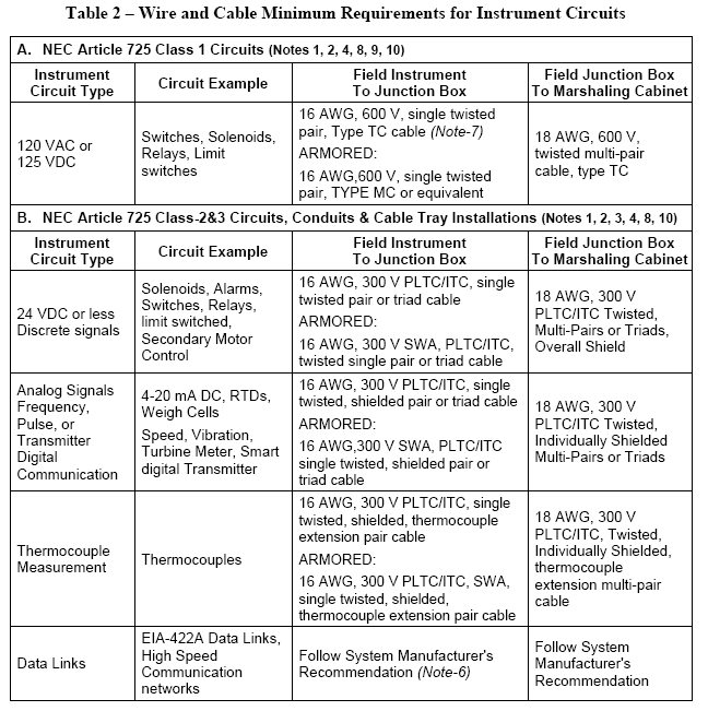
- Cables used for Instrumentation Signals shall be selected per Table 2, SAES-J-902 section 12 para. 12.2.
INSIDE PANELS TERMINATION
- For Cable Termination inside building refer to detail installation VA-539135-059.
- All conductors/pairs cable shall be terminated adjacent to each other on the same terminal strip in the marshaling cabinet.
- Drain wire or shield shall be insulated by green color heat shrinkable tube and shall also be individually terminated at these location.
- The shield shall be grounded at one point only, typically at the marshaling cabinet in the control room or process interface building.
- Each group of cable carrying similar signals shall contain a minimum of 20% spare pairs or triad.
- Cable entering the marshaling cabinet shall be cut to the appropiate lengths. Coiling extra cable length or spare pair/triads beneath the marshaling cabinet is not acceptable.
CABLE TAGGING and LABELLING
- All cables shall be tagged, at each end, with a cable-tag.
- Homerun cables shall be tagged with assigned “IC” cable number.
- Cable-tags outside junction boxes and marshalling cabinets shall be SS316 with permanently marked alphanumeric characters i.e., raised or stamped characters. The cable-tag shall be securely attached to the cable with nylon coated 316 stainless-steel cable ties as per SAES-J-902 Para.5.7.1. Where cable tags are required inside junction boxes or marshalling cabinets (i.e., cables extended in conduits), weather resistant, high quality plastic cable tags secured using cable ties per SAES-J-902 Para.5.7.2 may be used.
- Each wire tag shall have two labels. The first label (closest to the end of the wire) shall identify the terminal number to which the wire is physically connected. The other label shall be the terminal number of the connection of the opposite end of the wire.
- Where wires terminate on instrument or device terminals, the instrument tag number and terminal designation (+) or (-), shall be used in lieu of terminal strip identification.
- Wire tag information shall be permanently marked in block alpha numeric or typed on tubular, heat-shrinkable, slip-on sleeves. Wrap-around, snap-on or self-adhesive wire markers shall not be used. Handwritten wire tags are not acceptable.
- A clear heat shrink sleeve shall be installed over the wire tag for all instruments that use rust preventive grease on its threaded wiring access cover.
- Spare pairs/triads in multi-pair/triad cables shall be labeled “Spare” in addition to the destination and source terminal numbers. The “Spare” designation shall be on a separate wire tag installed on the twisted pair and not part of the source/destination tag.