Proximity Probes and Related Accessories
Introduction
This guideline provides machinery instrumentation engineers, field instrument technicians and plant maintenance personnel with recommendations for the installation of Bently Nevada proximity probes and related accessories.
Installation of Transducer Hardware and Probe Installation
Forethought must be given to proper selection of the proximity probe mounting locations.
General Considerations
The observed surface must be free of all irregularities (i.e., scratches, rust and corrosion, out-of-roundness, chain marks, etc.). Irregularities cause a change in probe gap which is not shaft position change, thus introducing a signal error and limiting transducer accuracy.
Consideration must also be given to the shaft material. The Proximitor® response is similar for most common shaft steel alloys; however, some materials have different surface areas which present varying values of resistivity. This can also introduce a “noise” signal on the Proximitor® output. Bently Nevada Corporation can provide transducers calibrated for a large number of shaft materials (we have more than 100 materials in stock). Some shaft surface treatments (chrome plating, metallizing, etc.) are thin enough to allow the probe eddy currents to penetrate down to the parent shaft materials, thus “seeing” two different material resistivities as well as the normally rough interface surface between the shaft and the surface treatment. Information concerning the nature of shaft materials and surface finish has been well documented and should be consulted before installing probes on a machine in the field.
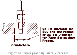
A probe tip with sufficient clearance should be provided so that the probe field only interprets the shaft motion. Proper side clearance equal to 2X (3X for 7200 Series 5 mm probes) should be maintained. Probes should not be mounted in an area where axial and/or radial shifts or thermal growth of the rotor will cause the probe to observe an irregular surface or which will result in an interference with side clearance.
Probes are compatible with most petrochemical environments and will resist attack from chemicals have a pH rating to 4 to 10. Strong acids with a pH rating greater than 10, and some organic solvents (such as dimethyl formamide) may cause damage to the probes. Bently Nevada can provide special probes designed to operate in harsh chemical environments.
In machinery where high temperatures exist around the probe location, it may be necessary to route the probe lead and extension cable inside lubrication oil lines or other areas that will not exceed 176.7 deg C (350 deg F). This is common on the exhaust end of gas turbines.
Mount probes sufficiently apart from one another to prevent cross talk between probes (See Figure). 3000 Series probes should be kept at least 25 mm (1.0 inch) apart from each other while 7200 Series probes should be kept 40 mm (1.6 inches) apart.
Bently Nevada probes are designed to operate with 1000/ 4000 Series carbon steel and most magnetic steels commonly used in rotating machinery. The transducer is calibrated at the factory using an AISI 4140 steel target.
Note: Proximity transducers can be provided to operate with any conductive metal. If the observed metal is other than 1000/4000 Series carbon steel, Bently Nevada should be contacted as the transducer will require special calibration.
Specific Considerations
Note: Reference is made to the American Petroleum Institute (API) document number 670 where applicable.
Radial Vibration
Throughout the machine train it is desirable to laterally mount the XY probes in the same radial plane to simplify comparative measurements from plane-to-plane (API 670), and provide additional protection from single plane motion.
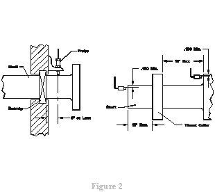
Mount the radial probes near radial bearing (API 670; see Figure 2), avoiding nodal point (typically two) at which the shaft will not indicate any vibration. A perfectly normal machine may exhibit high vibration amplitudes when observation is made some distance from the bearing due to mode shape.
Note: During the operating life of a machine rotor, nodal points will change location. If vibration levels decrease over an extended period of time it is possible the nodal points have shifted toward the probe location. Nodal locations should be verified and only then should any consideration be given to probe relocation. Nodal points will normally move out with increasing vibration.
Another set of probes mounted away from the bearing will provide additional dynamic motion information about mode shape.
Axial Position Or Thrust Position
Mount axial (thrust) probes within 300 mm (12 inches) of the thrust bearing (API 670, see Figure 2 ). When probes are mounted farther away, thermal growth or other changes not related to thrust bearing protection may give misleading information regarding the thrust bearing condition.
When two (2) axial probes in a dual voting arrangement are used for automatic trip service at least one (1) of them should observe a surface that is integral to the rotor. If a thrust collar becomes loose on the rotor, the axial probe observing that collar will no longer measure true rotor movement.
Most turbines will require that the probe be placed on the steam inlet shaft end, inboard or outboard of the thrust collar.
Keyphasor
Mount Keyphasor® probes radially, not axially. Axial (thrust) movement may cause excessive voltage changes at the Proximitor® output, inhibiting proper Keyphasor® pulse amplitude.
Observe a notch or projection of sufficient size to create a large voltage pulse, Bently Nevada recommends that proximity probes observe a notch or projection of 4140 material (length two probe tip diameters; depth .060 inch; width 1.5X the probe tip diameter). The pulse should then be at least 5 volts peak to peak.
Mount the Keyphasor® probe on the driver of the machine train. This will allow the driver to be run while uncoupled from the load.
Mount one (1) Keyphasor® probe per each machine speed. If a gear increaser or reducer is used, two (2) Keyphasor® probes are recommended, one on each side of the gear box.
Eccentricity Position
The radial vibration probes mounted at the radial bearings can be used simultaneously for radial vibration and eccentricity position (the average position of the shaft in the radial bearing). When probes are mounted away from the radial bearings, exercise caution because the result is pseudo eccentricity, which can be influenced by thermal growth and shaft mode shape.
Eccentricity Slowroll (Shaft Bow Measurement)
A single probe mounted away from the bearing is recommended to observe greater deflection for the eccentricity peak to peak slowroll measurement (shaft thermal or permanent bow). Some indication of bow can be given be observed at that lateral location along the machine train.
Installation Considerations and Practices
Bently Nevada probes are designed to accept normal field treatment but reasonable care must be taken in handling and installing them. The installation recommendations outlined in this section apply to both radially and axially mounted probes. They have been developed from the experience gained through many years of installing probes and deserve careful review.
Before installing a probe, make sure the tapped hole is free of foreign material and the threads are clean and in good condition. If in doubt, use an appropriate tap to clean the threads. As the probe is threaded into the mount, the probe lead should be free to turn to prevent a torque (twisting) load between it and the probe case. The probe threads should be marked so that connection to the extension cable (for voltage readings) will not be necessary until the probe almost enters its linear range. Be sure to allow the probe cable to turn with the probe.
Because the probe “sees” to the side, there should be no metal within an approximate distance of 1/2 x (1X for 7200 Series 5 mm probes) the tip diameter of the probe face, except the observed surface. Counterboring, chamfering or other relieving may be necessary to achieve proper lateral clearance for the probe tip (See Figure 4).
The probe is threaded into its mounting until the desired gap (i.e., center or the available linear range of the transducer) between the probe and observed surface is obtained. The gap can be measured mechanically with a feeler gauge. It can also be measured more accurately electrically be connecting the probe to an extension cable and Proximitor and then observing the indicated transducer output voltage. By cross-referencing this voltage value to the probe calibration curve, the gap is determined. The electrical measurement technique can be used to gap probes when the gap cannot be physically measured.
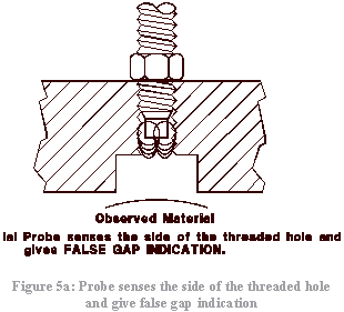
Note: As the probe tip is threaded, the transducer output voltage will remain low while the probe tip is sensing the surrounding threaded mount. Once the probe tip extends past the threaded mount, the transducer output voltage will increase to a greater value (see Figure 5a).
However, as the tip extends farther and approaches the observed surface, the transducer output will decrease as shown on the calibration curve; zero volts will be encountered 10 – 30 mils (0.25 – 0.80 mm) before shaft surface contact with the 3000 Series probe and less than 1 volt below 10 mils (0.25 mm) with the 7200 Series probe.
Caution:
To prevent damage to the probe tip, make sure it does not physically contact the observed surface of the rotating shaft.
Turn in the probes to the second minimum voltage level or when the probe tip approaches the shaft (Figure 5b) then back out to the proper probe gap voltage. With the probe gap set, secure the probe in position with a locknut or equivalent device. Do not exceed 8.1 N·m (6 ft.-lb.) of torque on 1/4-28 thread, nor 33.9 N·m (25 ft.-lbs.) on a 3/8-24 tread. Loctite may also be used.
Note: This procedure is recommended for vibration probes and not Keyphasor® probes. It is recommended that the machine shaft be at rest and that the probe not be positioned over the notch or projection to be observed for Keyphasor® probe installation. Of course, axial position probes should be gapped when the machine is not running so that the rotor can be placed at a know position with respect to the clearances in the thrust bearing.


carry on the ѕuperb work!