This article is about Pushbutton and Pilot Light Control Stations & Accessories Materials Selection & Requirements of General Boxes and Enclosures for Electrical Power System Systems as per International Codes and standards for Commercial Buildings, Plants and Refinery Projects.
Pushbutton and Pilot Light Control Stations & Accessories Materials Selection & Requirements
Certification & 3rd Party Listing – General Purpose Boxes & Enclosures
- Box and Enclosure Certification:
In outdoor plant areas, equipment and terminal enclosures shall be:
(a) NEMA 250/NEMA ICS 6 Type 4; or
(b) NEMA Type 3 manufactured copper free cast aluminum (0.4 of 1% maximum), or plastic (including fiberglass); or
(c) IEC 60529 Type IP54 or better” - Box and Enclosure Certification:
In outdoor plant areas, outside the perimeter of process units, and other industrial areas, equipment and terminal enclosures shall be:
(a) NEMA Type 3 or 4; or
(b) IEC 60529 Type IP54 or better” - Box and Enclosure Certification:
In outdoor plant and other industrial areas located in severe corrosive environments as defined in Paragraph 4.2, equipment and terminal enclosures shall be:
(a) NEMA Type 4X (except galvanized and/or painted or coated carbon steel sheet metal enclosures are not permitted); or
(b) NEMA Type 3 or 4, manufactured of copper free cast aluminum (0.4 of 1% copper maximum), or plastic (including fiberglass); or
(c) IEC 60529 Type IP 54 or better, manufactured of stainless steel (Type 304 or better), copper free cast aluminum, or plastic (including fiberglass).
Commentary Note:
In outdoor plant and other industrial areas located in severe corrosive environments, paragraph 7.3 supersedes paragraphs 7.1 and 7.2.” - General Box and Enclosure Certification:
In outdoor non-industrial areas, equipment and terminal enclosures shall be:
(a) NEMA Type 3R, 3 or 4; or
(b) IEC 60529 Type IP34 or better.
Certification & 3rd Party Listing & Labeling – Explosion Proof Boxes & Enclosures
- Box and Enclosure Labeling, Listing or Certification:
Boxes installed in hazardous (classified) areas, that are required by the National Electrical Code (NEC) to be approved (except conduit sealing fittings) shall be labeled or listed or certified by any of the agencies listed in SAES-P-100 Table 2 (See Attachment 1). - “Suitability: Suitability of identified equipment shall be determined by one of the following:
(1) Equipment listing or labeling
(2) Evidence of equipment evaluation from a qualified testing laboratory or inspection agency concerned with product evaluation
(3) Evidence acceptable to the authority having jurisdiction such as a manufacturer’s self-evaluation or an owner’s engineering judgment.
[NFPA 70, NEC 500.8(A)]” - Equipment Marking:
Equipment shall be marked to show the environment for which it has been evaluated. Unless otherwise specified or allowed in NEC 500.8(C)(6), the marking shall include the information specified in (C)(1) through (C)(5) (See Below):
(1) Class
(2) Division
(3) Material Classification Group
(4) Equipment Temperature
(5) Ambient Temperature Range
[NFPA 70, NEC 500.8(C)]” - Equipment Temperature:
The marking shall specify the temperature class or operating temperature at a 40°C ambient temperature, or at the higher ambient temperature if the equipment is rated and marked for an ambient temperature of greater than 40°C.
Exception: Equipment of the non–heat-producing type, such as junction boxes, conduit, and fittings, and equipment of the heat-producing type having a maximum temperature not more than 100°C shall not be required to have a marked operating temperature or temperature class.
[NFPA 70, NEC 500.8(C)(4)]” - Equipment Temperature:
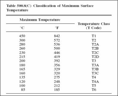
The temperature class, if provided, shall be indicated using the temperature class (T Codes) shown in Table 500.8(C) (Attachment 2). Equipment for Class I and Class II shall be marked with the maximum safe operating temperature, as determined by simultaneous exposure to the combinations of Class I and Class II conditions.
[NFPA 70, NEC 500.8(C)(4)]” - Class I Temperature:
The temperature marking specified in Table 500.8(C) (Attachment 2) shall not exceed the ignition temperature of the specific gas or vapor to be encountered.
[NFPA 70, NEC 500.8 (D)(1)]”
Installations in hazardous locations shall be per the National Electrical Code, with additions and exceptions that EEx or Ex marked equipment certified or approved by one of the agencies listed in Table 2 (Attachment 1) is acceptable. - Approval for Class and Properties:
Box and Enclosure shall be identified not only for the class oflocation but also for the explosive, combustible, or ignitible properties of the specific gas, vapor, dust, or fibers/flyings that will be present. In addition, Class I equipment shall not have any exposed surface that operates at a temperature in excess of the ignition temperature of the specific gas or vapor. [NFPA 70, NEC 500.8(B)(1)]”
Control Stations intended for installation in a hazardous (classified) area shall be labeled or listed by a third party certifying agency as suitable for the environment.
Material Requirements
- New and Unused: General Boxes, Enclosures and accessories shall be new and unused.
- As Designed: General Boxes and Enclosures and accessories shall be in accordance with the Saudi Aramco-approved project-specific design drawings, diagrams, schedules, lists, databases, and associated design documents.
- Free of Damage: General Boxes and Enclosures and accessories shall be free of damage.
- QC Before Installation: General Boxes and Enclosures and accessories shall conform to all applicable requirements, standards, and specifications prior to release to be used as part of the work.
- Traceability – General Boxes and Enclosures and accessories shall be traceable from the manufacturer and supplier through delivery, storage, fabrication, erection, installation, repair, modification and use.
- “Severe corrosive environments include:
a) Outdoor offshore locations
b) Outdoor onshore locations within one kilometer from the shoreline of the Arabian Gulf, all of the Ras Tanura Refinery and Terminal, and within three kilometers from the shoreline of the Red Sea.
c) Location where chlorine or other corrosive chemicals are being handled (e.g., waste water treatment, water treatment, R.O. facilities).
d) Battery Rooms” - “Locations where chemicals are being handled, enclosures, conduits, fittings, and wirings must be resistant to the chemicals present.
Commentary Note:
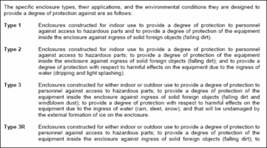
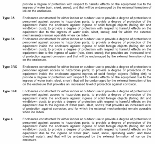
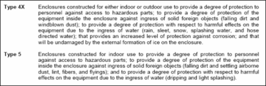
A structure enclosed by walls on three sides only, and has a roof, is considered an outdoor location. A non-airconditioned building is considered an indoor location. A shop that has its doors kept open to facilitate entry of vehicles is considered an indoor location.” - “Types of Electrical enclosure rated not more than 1000 Volts:
a. Non-hazardous locations
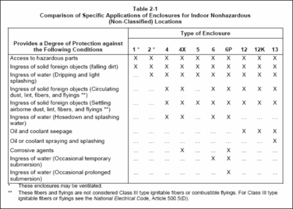
1. Enclosures for indoor locations, Types 1, 2, 5, 12, 12K, and 13; and
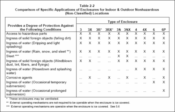
2. Enclosures for indoor or outdoor locations, Types 3, 3X, 3R, 3RX, 3S, 3SX, 4, 4X, 6, and 6P.
b. Hazardous locations
1. Enclosures for indoor locations, Types 7 and 9;
2. Enclosures for indoor or outdoor locations, Type 8; and
3. Enclosures for mining applications, Type 10
Table 2-1 and 2-2 (Attachment 3) are guides for comparing specific applications of enclosures.
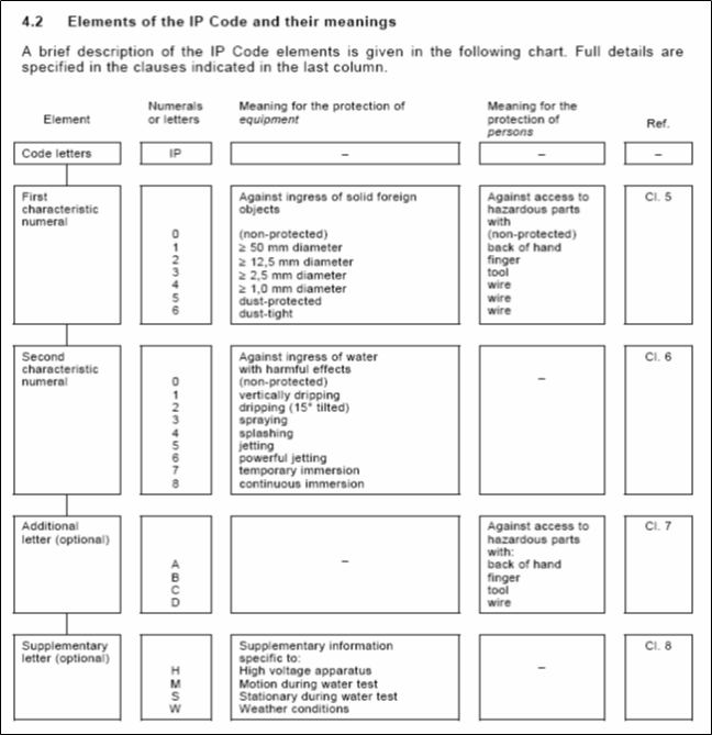
[NEMA 250 Sec. 1.1]” - “The IP Code & Designations:
A coding system to indicate the degrees of protection provided by an enclosure against access to hazardous parts, ingress of solid foreign objects, ingress of water and to give additional information in connection with such protection. Designations of the degree of protection provided by an enclosure is indicated by the IP Code arranged (See attachment 6 & 7). [IEC 60529 Sec. 3.4 & 4]” - “Drainage Openings:
Type 2, 3R, and 3RX enclosures shall have provisions for drainage. Drainage openings shall not be less than 3.2 mm in diameter (1/8 inch in diameter) or more than 6.4 mm in diameter (1/4 inch in diameter) unless baffled or provided with a drainage fitting.
For Type 2, 3R, and 3RX enclosures that also meet the requirements of other enclosure types, the drainage openings shall be closed by a removable plug. The enclosure shall meet the requirements of the other enclosure types with the plug installed.
[NEMA 250 Sec. 3.6.3]” - “Gaskets: A gasket shall be secured with adhesive or by mechanical means. The gasket and its securing means shall not be damaged when the gasketed joint is opened.
[NEMA 250 Sec. 3.14]”
An enclosure shall completely enclose all live parts that may be housed in it. [UL 50 Sec. 6.1.1 and NEMA 250 Sec. 1.2]
An edge on an enclosure shall not be sufficiently sharp to constitute a risk of injury in normal maintenance or use. [UL 50 Sec. 6.1.4]
Verify that all junction boxes, pull boxes, and conduit bodies are correct (size/ type) in according to NEC 314.16 and table 314.6(A) (Attachment 5). [NFPA70, NEC 314.16]
Pushbutton and Pilot Light Control Stations – Installation and Pre-Commissioning
- “Control and instrument transfer switch handles or pushbuttons other than those covered in 490.41(B) shall be in a readily accessible location at an elevation of not over 2.0 m (78 in.).
Exception: Operating handles requiring more than 23 kg (50 lb) of force shall be located no higher than 1.7 m (66 in.) in either the open or closed position.
[NFPA, NEC 490.41(A)]” - “Operating handles for infrequently operated devices, such as drawout fuses, fused potential or control transformers and their primary
disconnects, and bus transfer switches, shall be permitted to be located where they are safely operable and serviceable from a portable platform. [NFPA 70, NEC 490.41(B)]” - “Where multiconductor cable is used with a suspended pushbutton
station, the station shall be supported in some satisfactory manner that protects the electrical conductors against strain.
[NFPA 70, NEC 610.11(D)]” - “Where a pushbutton is used as a means to disconnect power, pushing the button in shall disconnect the power.
[NFPA 70, NEC 645.10]” - “A Pendant pushbutton with nonconductive supporting means and having nonconductive surfaces or ungrounded exposed conductive surfaces shall be employed on a remote crane or hoist controls that could introduce hazardous electrical conditions into the cell line working zone
[NFPA 70, NEC 668.32(B3)]” - “Conductors shall be enclosed in raceways or be Type AC cable with insulated grounding conductor, Type MC cable, or Type MI cable unless otherwise permitted or required below.
Where multiconductor cable is used with a suspended pushbutton
station, the station shall be supported in some satisfactory
manner that protects the electrical conductors against strain.
[NFPA 70, NEC 610.11(D)]”
Factory sealed multigang push button and similar control stations having an internal volume exceeding 2,000 cm³ are exempted from the requirement of providing with Type 300 Series stainless steel breather and drain fittings, or a combination breather and drain fitting. - “Switch or contactor enclosures shall not be used as junction boxes or as raceways for conductors feeding through or tapping off to other switches, unless special designs are used to provide adequate space for this purpose.
[NFPA 70, NEC 110.59]”
“Instruments, pilot lights, potential transformers, and other switchboard
devices with potential coils shall be supplied by a circuit that is protected by standard overcurrent devices rated 15 amperes or less.
[NFPA 70, NEC 408.52]”
“Remotely Controlled:
Devices are operated electrically from a pilot-type control console or panel. Pilot control panels either shall be part of the switchboard or shall be permitted to be at another location.
[NFPA 70, NEC 520.26(B)]” - “Pilot Light:
A pilot light shall be provided within the enclosure and shall be connected to the circuit supplying the board so that the opening of the master switch does not cut off the supply to the lamp. This lamp shall be on an individual branch circuit having overcurrent protection rated or set at not over 15 amperes.
[NFPA 70, NEC 520.53(G)]” - “Diffraction and Irradiation Types:
Diffraction and irradiation type equipment or installations not effectively
enclosed or not provided with interlocks to prevent access to live current-carrying parts during operation shall be provided with a positive means to indicate when they are energized. The indicator shall be a pilot light, readable meter deflection, or equivalent means.
[NFPA 70, NEC 660.23(B)]”
Control Station enclosure intended to be installed in a severe corrosive environment (as defined by SAES-P-100 Sec. 8) shall have additional anti-corrosive properties.
Control Stations intended for installation in a hazardous (classified) area shall be labeled or listed by a third party certifying agency as suitable for the environment.
When pilot lights are specified on the design drawings, Separate red and green colored lights shall be used to indicate motor operation status.
Pilot light fixture design shall be able to withstand continuous shorting of the lamp terminals without affecting controller functionality.
Pilot light lamps shall be high density LED (Light Emitting Diode) type providing a light intensity similar to an incandescent fixture.
Pushbuttons shall not be designed, or equipped with features, capable of accepting padlocks. - “The voltage rating of the indicating lights shall not be less than the
nominal voltage of a circuit to which it is connected, as specified on the design drawings and Purchase Order.
[NFPA 70, NEC 110.4]”
Pilot lights and pushbuttons shall meet the requirements of NEMA ICS 5, Part 5.
Pilot lights and pushbuttons shall be heavy duty and oil tight.
Pilot lights and pushbuttons shall have the same, or better, environmental/corrosion resistance rating as the enclosure in which they are mounted.
Pushbuttons contact ratings shall be a minimum of A600/P600. - “Control, metering and protection devices, with manual features which
are operable with the compartment doors closed, (e.g., selector switches, pushbuttons, protective relays, etc.) shall be mounted a
maximum of 2000 mm from the base of the switchrack.” - “The activation of a STOP/OFF device (e.g., STOP pushbutton/switch,
overload contact, relay contact, etc.) shall instantaneously open the
contactor poles.”
Boxes and Enclosures – Class I, Division 2 or Zone 2 – Pushbutton Installation and Pre-commission
- “Class I, Division 1:
In Class I, Division 1 locations, switches, circuit breakers, motor controllers, and fuses, including pushbuttons, relays, and similar devices, shall be provided with enclosures, and the enclosure in each case, together with the enclosed apparatus, shall be identified as a
complete assembly for use in Class I locations.
[NFPA 70, NEC 501.115(A)]” - “Isolating Switches:
Fused or unfused disconnect and isolating switches for transformers or capacitor banks that are not intended to interrupt current in the normal performance of the function for which they are installed shall be
permitted to be installed in general-purpose enclosures.
[NFPA 70, NEC 501.115(B)(2)]” - “Fuses:
For the protection of motors, appliances, and lamps, other than as provided in 501.115(B)(4), standard plug or cartridge fuses shall be permitted, provided they are placed within enclosures identified for the location; or fuses shall be permitted if they are within general-purpose enclosures, and if they are of a type in which the operating
element is immersed in oil or other approved liquid, or the operating element is enclosed within a chamber hermetically sealed against the entrance of gases and vapors, or the fuse is a nonindicating, filled, current-limiting type.
[NFPA 70, NEC 501.115(B)(3)] - [NFPA 70, NEC 501.115(B)(3)]”
Control Stations intended for installation in a hazardous (classified) area shall be labeled or listed by a third party certifying agency as suitable for the environment. - “Where specifically permitted in Articles 501 through 503, general-purpose equipment or equipment in generalpurpose enclosures shall be permitted to be installed in Division 2 locations if the equipment does not constitute a source of ignition under normal operating conditions.
[NFPA 70, NEC 500.8(B)(3)]” - “Equipment marking shall specify the applicable material classification group(s) in accordance with 500.6.
Exception: Fixed luminaires marked for use only in Class I, Division 2 or Class II, Division 2 locations shall not be required to indicate the group.
[NFPA 70, NEC 500.8(C)(3)]”
“Equipment Marking – General-Purpose Equipment:
Fixed general-purpose equipment in Class I locations, other than fixed luminaires, that is acceptable for use in Class I, Division 2 locations shall not be required to be marked with the class, division, group,
temperature class, or ambient temperature range.
[NFPA 70, NEC 500.8(C)(6)]” - “Protection Techniques:
Nonincendive circuit, nonincendive equipment and nonincendive component protection techniques shall be permitted for equipment in Class I, Division 2; Class II, Division 2; or Class III, Division 1 or 2 locations.
[NFPA 70, NEC 500.7(F,G,H)]” - “The Oil Immersion protection technique shall be permitted for current-interrupting contacts in Class I, Division 2 locations as described in 501.115(B)(1)(2).
[NFPA 70, NEC 500.7(I)]” - “The Hermetically Sealed protection technique shall be permitted for equipment in Class I, Division 2; Class II, Division 2; or Class III, Division 1 or 2 locations
[NFPA 70, NEC 500.7(J)]” - “Inadequate Ventilation:
In a Class I, Division 1 location that is so classified due to inadequate ventilation, electrical equipment suitable for Class I, Division 2 locations shall be permitted.
[NFPA 70, NEC 500.7(K)(1)]” - “Interior of a Building:
In a building located in, or with an opening into, a Class I, Division 2 location where the interior does not contain a source of flammable gas or vapor, electrical equipment for unclassified locations shall be
permitted.
[NFPA 70, NEC 500.7(K)(2)]” - “Interior of a Control Panel:
In the interior of a control panel containing instrumentation utilizing or measuring flammable liquids, gases, or vapors, electrical equipment
suitable for Class I, Division 2 locations shall be permitted.
[NFPA 70, NEC 500.7(K)(3)]”
Boxes and Enclosures – Class I, Division 1 or Zone 1 – Conduit Seals for Pushbutton Enclosures installation and
Pre-commissioning
- “Conduit Seals, Class I, Division 1:
In Class I, Division 1 locations, conduit seals shall be located in accordance with 501.15(A)(1) through (A)(4).
[NFPA 70, NEC 501.15(A)]” - “Entering Enclosures:
Conduit seals shall be located in each conduit entry into an explosionproof enclosure where either of the following apply:
(1) The enclosure contains apparatus, such as switches, circuit
breakers, fuses, relays, or resistors, that may produce arcs, sparks, or high temperatures that are considered to be an ignition source in normal operation.
(2) The entry is metric designator 53 (trade size 2) or larger and the enclosure contains terminals, splices, or taps.
For the purposes of this section, high temperatures shall be considered to be any temperatures exceeding 80 percent of the autoignition temperature in degrees Celsius of the gas or vapor involved.
[NFPA 70, NEC 501.15(A)(1)]” - “Exception to 501.15(A)(1)(1):
Seals shall not be required for conduit entering an enclosure where such switches, circuit breakers, fuses, relays, or resistors comply with one of the following:
(1) Are enclosed within a chamber hermetically sealed against the entrance of gases or vapors
(2) Are immersed in oil in accordance with 501.115(B)(1)(2)
(3) Are enclosed within a factory-sealed explosionproof chamber located within the enclosure, identified for the location, and marked “factory sealed” or equivalent, unless the enclosure entry is metric designator 53 (trade size 2) or larger
(4) Are in nonincendive circuits
[NFPA 70, NEC 501.15(A)(1)]” - “Factory-sealed enclosures shall not be considered to serve as a seal for another adjacent explosionproof enclosure that is required to have a conduit seal.
NFPA 70, NEC 501.15(A)(1)]” - “Conduit seals shall be installed within 450 mm (18 in.) from the enclosure. Only explosionproof unions, couplings, reducers, elbows, capped elbows, and conduit bodies similar to L, T, and Cross types that are not larger than the trade size of the conduit shall be permitted between the sealing fitting and the explosionproof enclosure.
[NFPA 70, NEC 501.15(A)(1)]” - “Pressurized Enclosures:
In each conduit entry into a pressurized enclosure where the conduit is not pressurized as part of the protection system. Conduit seals shall be
installed within 450 mm (18 in.) from the pressurized enclosure.
[NFPA 70, NEC 501.15(A)(2)] - [NFPA 70, NEC 501.15(A)(2)]”
“Two or More Explosionproof Enclosures:
Where two or more explosionproof enclosures for which conduit seals
are required under 501.15(A)(1) are connected by nipples or by runs of conduit not more than 900 mm (36 in.) long, a single conduit seal in each such nipple connection or run of conduit shall be considered sufficient if located not more than 450 mm (18 in.) from either enclosure.
[NFPA 70, NEC 501.15(A)(3)]”
When cables entering enclosures are required to be sealed by the NEC, they shall be sealed by means of barrier type cable glands, utilizing sealing compound, (EEx d) or MI cable. These are called explosion proof glands by some manufacturers, flameproof by others. - “Conductor Fill:
The cross-sectional area of the conductors permitted in a seal shall not exceed 25 percent of the cross-sectional area of a rigid metal conduit of the same trade size unless it is specifically identified for a higher
percentage of fill. [NFPA 70, NEC501.15(C)(6)]” - “Class I, Divisions 1 and 2:
Seals installed in Class I, Division 1 and Division 2 locations shall comply with 501.15(C)(1) through (C)(6).
[NFPA 70, NEC501.15(C)]” - “Fittings:
Enclosures for connections or equipment shall be provided with an integral means for sealing, or sealing fittings listed for the location shall be used. Sealing fittings shall be listed for use with one or more specific compounds and shall be accessible.
[NFPA 70, NEC 501.15(C)(1)]” - “Compound:
The compound shall provide a seal against passage of gas or vapors through the seal fitting, shall not be affected by the surrounding atmosphere or liquids, and shall not have a melting point of less than 93°C (200°F).
[NFPA 70, NEC 501.15(C)(2)]” - “Thickness of Compounds:
Except for listed cable sealing fittings, the thickness of the sealing compound in a completed seal shall not be less than the metric designator (trade size) of the sealing fitting expressed in the units of measurement employed, and in no case less than 16 mm (5⁄8 in.).
[NFPA 70, NEC 501.15(C)(3)]” - “Splices and Taps:
Splices and taps shall not be made in fittings intended only for sealing with compound, nor shall other fittings in which splices or taps are made be filled with compound.
[NFPA 70, NEC 501.15(C)(4)]” - “Assemblies:
In an assembly where equipment that may produce arcs, sparks, or high temperatures is located in a compartment separate from the compartment containing splices or taps, and an integral seal is provided where conductors pass from one compartment to the other, the entire
assembly shall be identified for the location. Seals in conduit connections to the compartment containing splices or taps shall be provided in Class I, Division 1 locations where required by 501.15(A)(1)(2).501.5(A)(1)(2).
[NFPA 70, NEC 501.15(C)(5)]”
Explosionproof Enclosures and Cable Seals, Class I, Division 1 – Installation and Pre-commissioning
- “Cable Seals, Class I, Division 1:
In Class I, Division 1 locations, cable seals shall be located according to
501.15(D)(1) through (D)(3).
[NFPA 70, NEC 501.15(D)]” - “At Terminations:
Cable shall be sealed at all terminations. The sealing fitting shall comply with 501.15(C). Multiconductor Type MC-HL cables with a gas/vaportight continuous corrugated metallic sheath and an overall jacket of
suitable polymeric material shall be sealed with a listed fitting after removing the jacket and any other covering so that the sealing compound surrounds each individual insulated conductor in such a manner as to minimize the passage of gases and vapors.
[NFPA 70, NEC 501.15(D)(1)]” - “Exception to [NFPA 70, NEC 501.15(D)(1)]:
Shielded cables and twisted pair cables shall not require the removal of the shielding material or separation of the twisted pairs, provided the termination is by an approved means to minimize the entrance of gases or vapors and prevent propagation of flame into the cable core.
[NFPA 70, NEC 501.15(D)(1)]” - “Cables Capable of Transmitting Gases or Vapors:
Cables in conduit with a gas/vaportight continuous sheath capable of transmitting gases or vapors through the cable core shall be sealed in the Division 1 location after removing the jacket and any other coverings so that the sealing compound will surround each individual insulated conductor and the outer jacket.
[NFPA 70, NEC 501.15(D)(2)]” - “Exception to [NFPA 70, NEC 501.15(D)(2)]:
Multiconductor cables with a gas/vaportight continuous sheath capable of transmitting gases or vapors through the cable core shall be permitted to be considered as a single conductor by sealing the cable in the conduit within 450 mm (18 in.) of the enclosure and the cable end
within the enclosure by an approved means to minimize the entrance of gases or vapors and prevent the propagation of flame into the cable core, or by other approved methods. For shielded cables and twisted pair cables, it shall not be required to remove the shielding material or separate the twisted pair.
[NFPA 70, NEC 501.15(D)(2)]” - “Cables Incapable of Transmitting Gases or Vapors:
Each multiconductor cable in conduit shall be considered as a single conductor if the cable is incapable of transmitting gases or vapors through the cable core. These cables shall be sealed in accordance with 501.15(A).
[NFPA 70, NEC 501.15(D)(3)]”
Flameproof (EEx d) non-barrier type cable glands, without sealing compound, are not acceptable. - “Drainage – Control Equipment:
Where there is a probability that liquid or other condensed vapor may be trapped within enclosures for control equipment or at any point in the
raceway system, approved means shall be provided to prevent
accumulation or to permit periodic draining of such liquid or condensed vapor.
[NFPA 70, NEC 501.15(F)(1)]”
General Boxes and Enclosures – Class I, Division 1 or Zone 1 – Hazardous Location Enclosures installation and
Pre-commissioning
- Meters, Instruments, and Relays:
In Class I, Division 1 locations, meters, instruments, and relays, including kilowatt-hour meters, instrument transformers, resistors, rectifiers, and thermionic tubes, shall be provided with enclosures identified for Class I, Division 1 locations. Enclosures for Class I, Division 1 locations include explosionproof enclosures and purged and pressurized enclosures.
[NFPA 70, NEC 501.105(A)]” - Wiring Method:
In Class I, Division 1 locations, the wiring of Threaded rigid metal conduit or threaded steel intermediate metal conduit shall be permitted.
[NFPA 70, NEC 501.10(A)(1a)]”
“Boxes and Fittings:
All boxes and fittings shall be approved for Class I, Division 1.
[NFPA 70, NEC 501.10(A)(3)]” - Switches, Circuit Breakers, Motor Controllers, and Fuses:
In Class I, Division 1 locations, switches, circuit breakers, motor controllers, and fuses, including pushbuttons, relays, and similar devices, shall be provided with enclosures, and the enclosure in each case, together with the enclosed apparatus, shall be identified as a
complete assembly for use in Class I locations.
[NFPA 70, NEC 501.115(A)]” - Control Transformers and Resistors:
In Class I, Division 1 locations, transformers, impedance coils, and resistors, together with any switching mechanism associated with them, shall be provided with enclosures identified for Class I, Division 1
locations in accordance with 501.105(A).
[NFPA 70, NEC 501.120(A)]” - Motors and Generators:
In Class I, Division 1 locations, motors, generators, and other rotating electrical machinery shall be Identified for Class I, Division 1 locations.
[NFPA 70, NEC 501.125(A)(1)]”
“Motors and Generators:
In Class I, Division 1 locations, motors, generators, and other rotating electrical machinery shall be totally enclosed type supplied with positive-pressure ventilation from a source of clean air with discharge to a safe area, so arranged to prevent energizing of the machine until ventilation has been established and the enclosure has been purged with at least
10 volumes of air, and also arranged to automatically de-energize the equipment when the air supply fails.
[NFPA 70, NEC 501.125(A)(2)]” - Motors and Generators:
In Class I, Division 1 locations, motors, generators, and other rotating electrical machinery shall be totally enclosed inert gas-filled type supplied with a suitable reliable source of inert gas for pressurizing
the enclosure, with devices provided to ensure a positive pressure in the enclosure and arranged to automatically de-energize the equipment when the gas supply fails.
[NFPA 70, NEC 501.125(A)(3)]” - Motors and Generators:
In Class I, Division 1 locations, motors, generators, and other rotating electrical machinery shall be designed to be submerged in a liquid that is flammable only when vaporized and mixed with air, or in a gas or vapor at a pressure greater than atmospheric and that is flammable only when mixed with air; and the machine is so arranged to prevent energizing it until it has been purged with the liquid or gas to exclude air, and also arranged to automatically de-energize the equipment when the supply of liquid or gas or vapor fails or the pressure is reduced to atmospheric.
[NFPA 70, NEC 501.125(A)(4)]” - Totally enclosed motors of the types specified in 501.125(A)(2) or (A)(3) shall have no external surface with an operating temperature in degrees Celsius in excess of 80 percent of the ignition temperature of the gas or vapor involved. Appropriate devices shall be provided to detect and automatically de-energize the motor or provide an adequate alarm if there is any increase in temperature of the motor beyond designed limits. Auxiliary equipment shall be of a type identified for the location in which it is installed.
[NFPA 70, NEC 501.125]” - Supports of Luminaires (Lighting Fixtures):
Boxes, box assemblies, or fittings used for the support of luminaires shall be identified for Class I locations.
[NFPA 70, NEC 501.130(A)(4)]” - Signaling, Alarm, Remote-Control, and Communications
Systems:
In Class I, Division 1 locations, all apparatus and equipment of signaling, alarm, remotecontrol, and communications systems, regardless of voltage, shall be identified for Class I, Division 1 locations, and all wiring shall comply with 501.10(A), 501.15(A), and 501.15(C).
[NFPA 70, NEC 501.150(A)]” - Grounding:
Wiring and equipment in Class I, Division 1 and 2 locations shall be grounded as specified in Article 250 and in accordance with the requirements of 501.30(A) and (B). [NFPA 70, NEC 501.30] - Bonding:
The locknut-bushing and double-locknut types of contacts shall not be depended on for bonding purposes, but bonding jumpers with proper fittings or other approved means of bonding shall be used. Such means of bonding shall apply to all intervening raceways, fittings, boxes, enclosures, and so forth between Class I locations and the point of grounding for service equipment or point of grounding of a separately derived system. [NFPA 70, NEC 501.30(A)]” - Exception to [NFPA 70, NEC 501.30(A)]:
The specific bonding means shall only be required to the nearest point where the grounded circuit conductor and the grounding electrode are connected together on the line side of the building or structure disconnecting means as specified in 250.32(A), (B), and (C), provided the branch-circuit overcurrent protection is located on the load side of the disconnecting means.
[NFPA 70, NEC 501.30(A)]” - Types of Equipment Grounding Conductors:
Flexible metal conduit and liquidtight flexible metal conduit shall not be used as the sole ground-fault current path. Where equipment bonding jumpers are installed, they shall comply with 250.102.
[NFPA 70, NEC 501.30(B)]” - Exception to [NFPA 70, NEC 501.30(B)]:
In Class I, Division 2 locations, the bonding jumper shall be permitted to be deleted where all of the following conditions are met:
(1) Listed liquidtight flexible metal conduit 1.8 m (6 ft) or less in length, with fittings listed for grounding, is used.
(2) Overcurrent protection in the circuit is limited to 10 amperes or less.
(3) The load is not a power utilization load
[NFPA 70, NEC 501.30(B)]” - Surge Protection:
In Class I, Division 1, surge arresters, surge-protective devices, and capacitors shall be installed in enclosures identified for Class I, Division 1 locations. Surge-protective capacitors shall be of a type designed for specific duty.
[NFPA 70, NEC 501.35]” - Increased safety (protection type “”e””) motors and terminal boxes are not permitted in Zone 1 locations.
Commentary Note:
The “”e”” protection method is acceptable if it is used in combination with the “”d”” protection method, if d”” is the primary protection method.” - Flameproof enclosures EEx d II are permitted in Class I, Division 1 locations as meeting the NEC requirements for approved enclosures, provided:
1) NEC requirements for cable entry are met;
2) the overall enclosure is flameproof EEx d II (explosion-proof) as a whole (not only its components);
3) the enclosure is constructed of a conductive metal or has an integral metal bonding device that ensures a positive low-resistance bond between conduits or/and cable armors entering or terminating at the enclosure; and
4) if used outdoors, the enclosure is rated a minimum of IP54.” - Equipment suitable for Class 1, Zone 0 locations may be used in Class 1, Division 1 locations.
- In hazardous (classified) locations, enclosures that are required to be approved for Class I locations by NEC Article 501 or 505, shall meet the hazardous area equipment application requirements of SAES-P-100 and the NEC, in addition to all applicable requirements of SAES-P-104 Sec. 7.1 to 7.4
International Standard and Codes for Non-Metallic Wireways and Accessories
- METHOD STATEMENT FOR TESTING & COMMISSIONING OF SWITCHGEAR
- Advanced Power and Energy Meters Technical Requirements
3. NFPA 70 – National Electrical Code (NEC).
4. SAES-P-104 – Wiring Methods and Materials.
5. SAES-P-100 – Basic Power System Design Criteria.
6. SAES-P-116 – Switchgear and Control Equipment.
7. 16-SAMSS-512 – Switchracks and Factory Built Assemblies – Low Voltage.
8. ANSI/IEC 60529 – Degrees of protection provided by enclosures (IP Code).
9. NEMA ICS 6 – Industrial Control & Systems Enclosures.
10. NEMA 250 – Enclosures for Electrical Equipment (1000 Volts Maximum).
11. UL 50 – Enclosures for Electrical Equipment, Non-Environmental Considerations.
1. Attachment 1: Table 2 – Certification Agencies for Equipment in Hazardous Areas – SAES-P-100

2. Attachment 2: Table 500.8(C) – Classification of Maximum Surface Temperature – NFPA 70
3. Attachment 3: Table 2-1 & Table 2-2 – Guides for Comparing Specific Applications of Enclosures – NEMA 250
4. Attachment 4: Specific Enclosure Types – NEMA 250

5. Attachment 5: Table 314.16(A) – Metal Boxes – NFPA 70

6. Attachment 6: Arrangement of the IP Code – IEC 60529
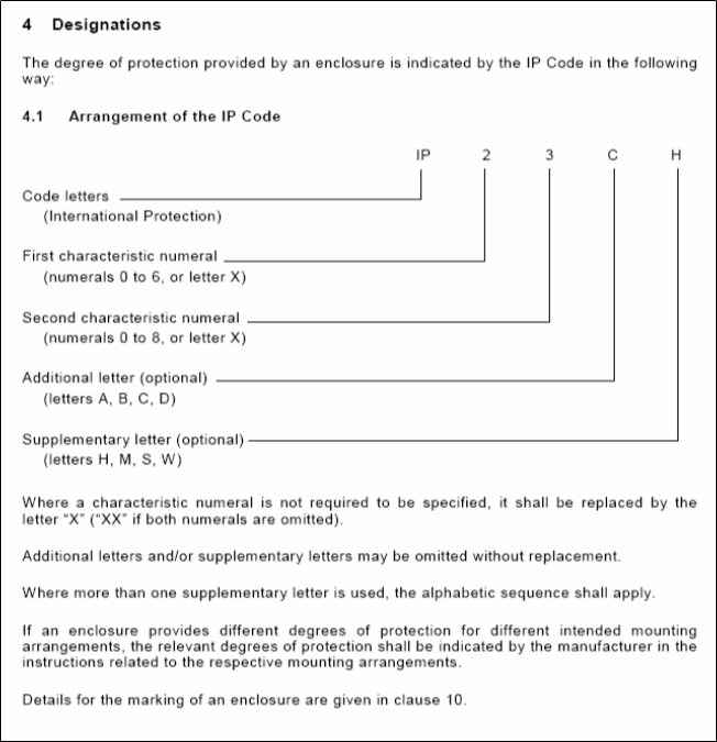
7. Attachment 7: Elements of the IP Code and their Meanings – IEC 60529